Method and observer for determining the exhaust manifold temperature in a turbocharged engine

Active Publication Date: 2013-07-11
FORD GLOBAL TECH LLC
View PDF7 Cites 11 Cited by
  • Summary
  • Abstract
  • Description
  • Claims
  • Application Information

AI Technical Summary

Benefits of technology

[0008]The disclosure involves the concept of constructing a fast and accurate T3 (=temperature upstream of the turbine) observer using a phenomenological/combustion-based T3 model, wherein the observer is robustified using a measurement of the temperature T4 (=temperature downstream of the turbine) and, as further described in the following, optionally a measurement or es

Problems solved by technology

However, since such temperature sensors are quite slow (with typical time constants of e.g. 1-2 s), a final steady state temperature measurement can take a significant amount of time of e.g. up to 10 s. Furthermore, alth

Method used


Image

  • Method and observer for determining the exhaust manifold temperature in a turbocharged engine
  • Method and observer for determining the exhaust manifold temperature in a turbocharged engine
  • Method and observer for determining the exhaust manifold temperature in a turbocharged engine

Examples


Embodiment Construction

[0014]According to an embodiment, the step of correcting the value of the manifold temperature is also based on a determination of the turbocharger speed. The turbocharger speed can be measured using a turbocharger speed sensor or estimated using a model.

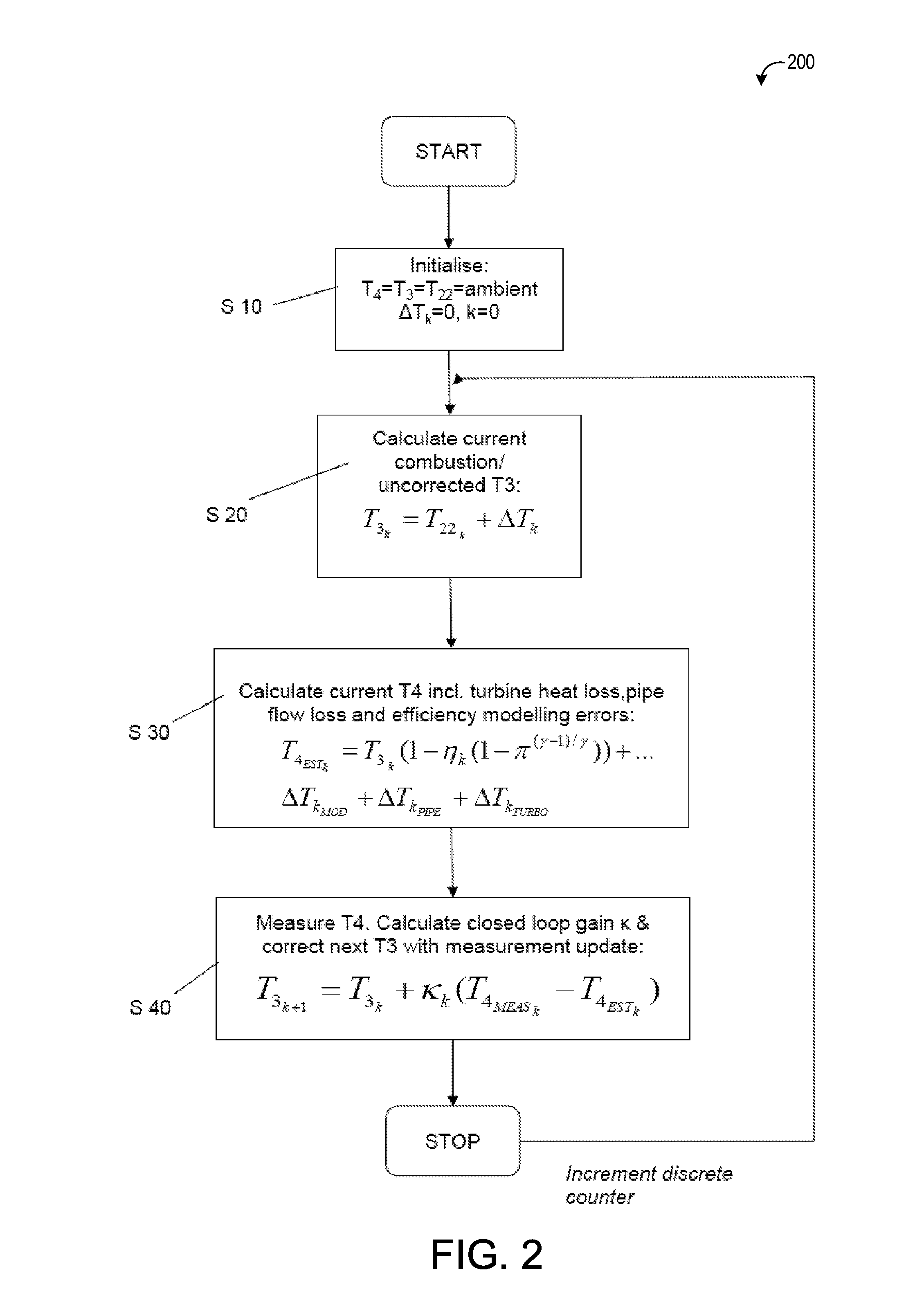
[0015]According to an embodiment, the step of correcting the value of the exhaust manifold temperature can be described by

T3NEW=T3OLD+κ(T4MEASNEW-T4ESTOLD)

[0016]wherein TdOLD denotes the uncorrected value of the exhaust manifold temperature (T3), κ denotes a gain factor,

T4MEASNEW

denotes the measured temperature (T4) downstream of the turbine and

T4ESTOLD

denotes an estimate of the temperature (T4) downstream of the turbine using the uncorrected value of the exhaust manifold temperature (T3).

[0017]According to an embodiment, the step of estimating a value of the exhaust manifold temperature based on a model can be described by

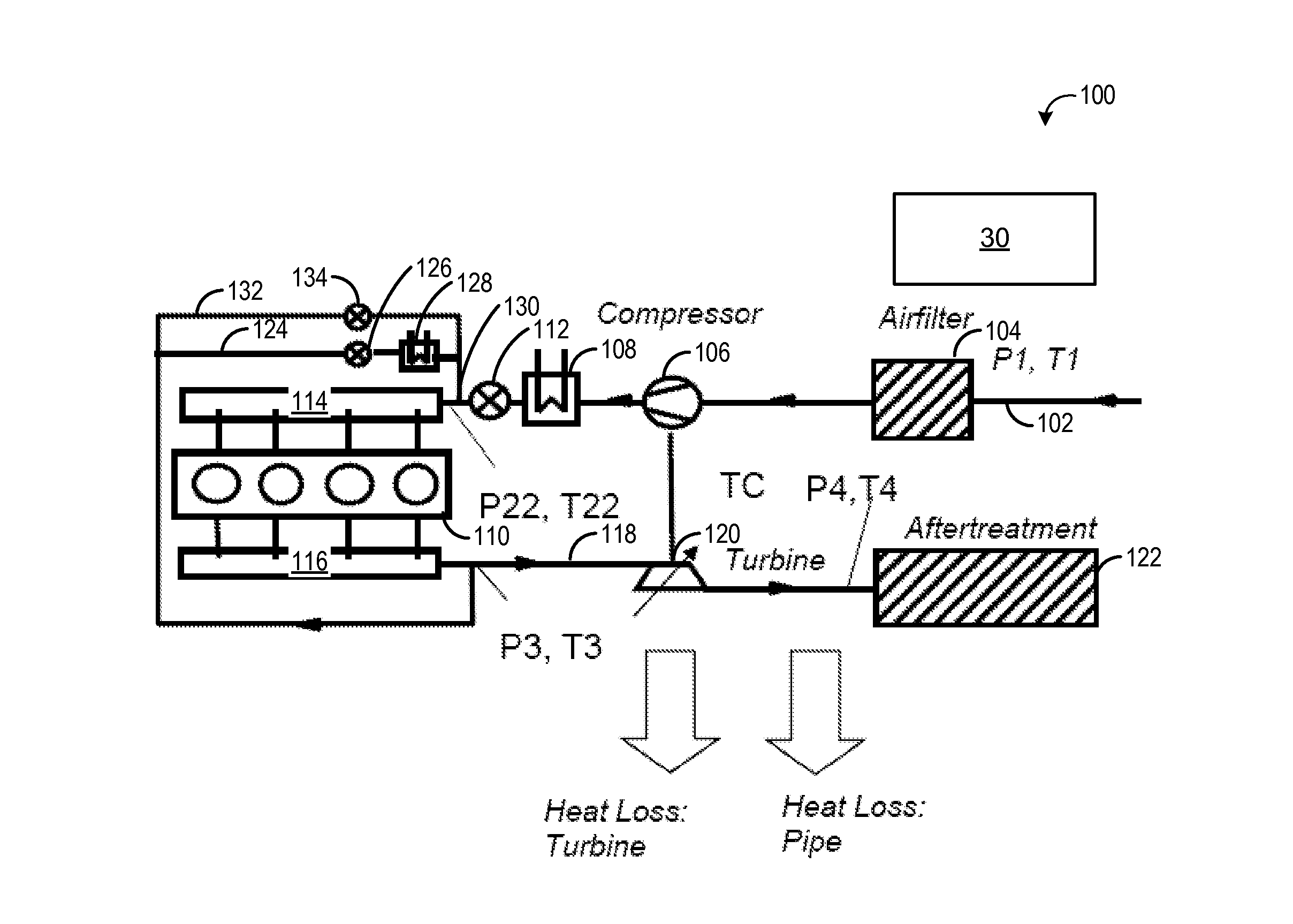
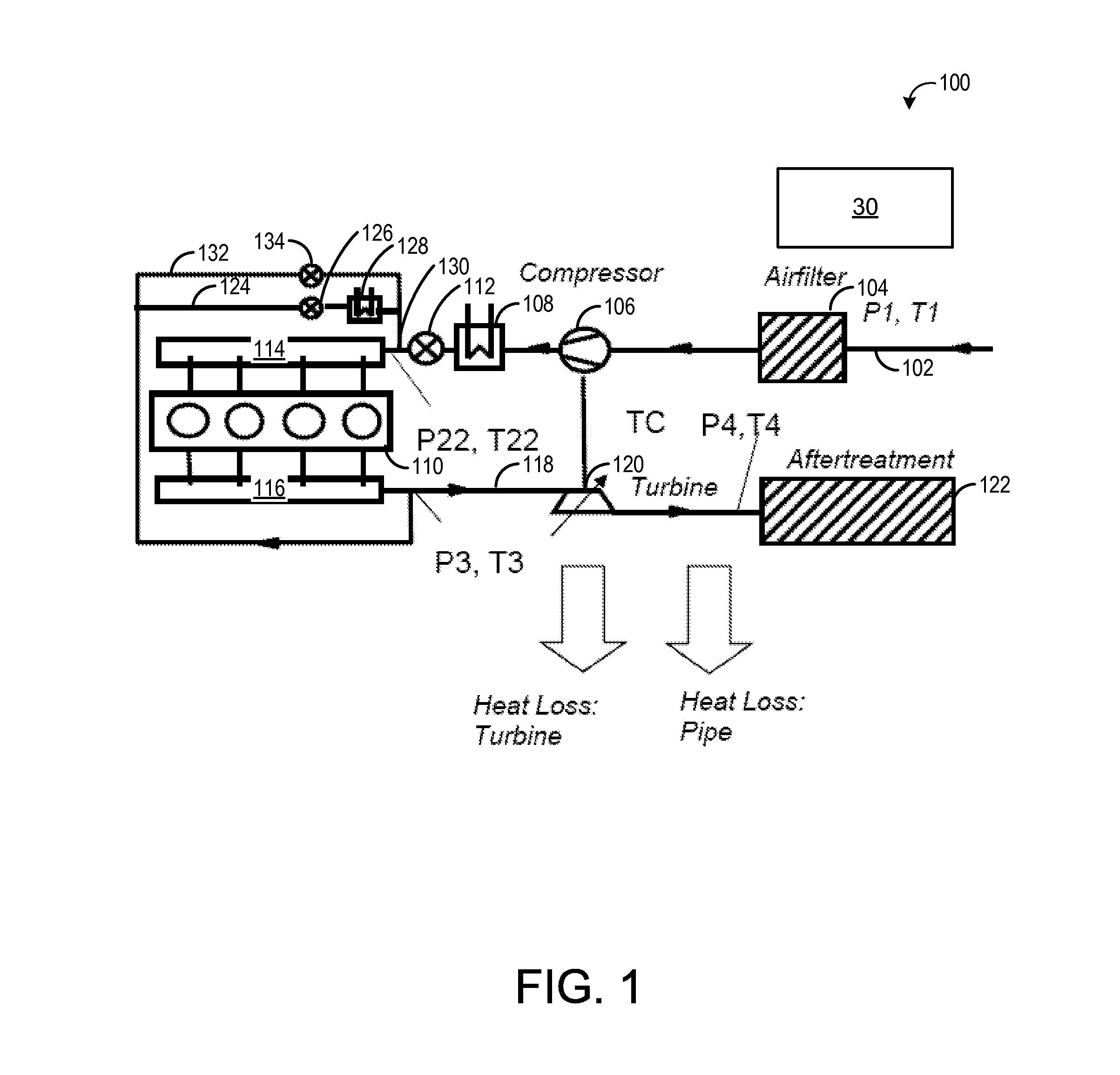
T3=T22+ΔT(N,λ,fuel,SOI, . . . )

[0018]wherein T22 denotes the temperature in the intake manifold downstream of a...


PUM


Abstract

The disclosure relates to a method and an observer for determining the exhaust manifold temperature in a turbocharged engine upstream of the turbine. In one example, a method for determining an exhaust manifold temperature in a turbocharged engine, said engine including a turbocharger and a turbine and said exhaust manifold temperature including a temperature upstream of the turbine, said method comprises estimating a value of the exhaust manifold temperature based on a model, measuring a temperature downstream of the turbine, and correcting the value of the exhaust manifold temperature based on said measurement.

Description

CROSS REFERENCE TO RELATED APPLICATIONS[0001]The present application claims priority to European Patent application 12150647.1, filed on Jan. 10, 2012, the entire contents of which are hereby incorporated by reference for all purposes.FIELD The present disclosure relates to a method and an observer for determining the exhaust manifold temperature in a turbocharged engine upstream of the turbine.BACKGROUND AND SUMMARY[0002]A recent trend in the automotive industry is to enhance the specific power, i.e. the peak power per engine displacement litre. This is achieved through either multi-turbocharging or mechanical supercharging or external boosting, such as e-boosting which makes use of an electrically driven compressor. Further approaches involve more efficient turbochargers with both higher compressor and turbine efficiencies and lower inertia. An industry-wide trend is the use of downsizing, driven by fuel consumption reduction requirements. This places requirements for turbocharger...

Claims


Application Information

Patent Timeline
IPC IPC(8): F02M25/07F02B47/08
CPCF02M25/07Y02T10/144F02B47/08F02D41/0007F02D41/1447F02D41/1446F02D2041/1416F02B2039/164F02B2039/168F02M26/00Y02T10/12
Inventor PETROVIC, SIMONVAN NIEUWSTADT, MICHIEL J.FULTON, BRIEN LLOYD
Owner FORD GLOBAL TECH LLC
Why Eureka
Try Eureka