
Vent structure for electromagnetic shielding

a technology of electromagnetic shielding and ventilation structure, which is applied in the direction of ventilation panels with screening provisions, cooling/ventilation/heating modifications, and screening casings, etc. it can solve the problems of electromagnetic wave exposure, electromagnetic wave damage, and the inability to properly ventilate, so as to improve the electromagnetic shielding performance, reduce the discharge of electromagnetic waves outside, and increase the distance of air containing electromagnetic waves.

Active Publication Date: 2013-07-11
ELECTRONICS & TELECOMM RES INST
View PDF7 Cites 8 Cited by
  • Summary
  • Abstract
  • Description
  • Claims
  • Application Information

AI Technical Summary

Benefits of technology

The patent describes various vent structures for electromagnetic shielding that aim to reduce the discharge of electromagnetic waves outside. These structures include a rectangular shielding duct with a discharge port and a vent, an electromagnetic wave absorption member on the inner surface of the shielding duct, and a plurality of zigzag-stacked shielding ducts or primary and secondary shielding ducts that face each other around the vent. These measures can further improve the electromagnetic shielding performance and protect against electromagnetic interference.

Problems solved by technology

Electromagnetic waves generated from such electronic devices have an effect on other electronic devices, and have become a factor that causes malfunction of devices due to mutual interference of electromagnetic waves between adjacent circuits.
Furthermore, as the spread of electromagnetic application devices rapidly increases, ordinary people, as well as workers in the manufacturing sector of electronic devices, are more frequently exposed to electromagnetic waves.
Electromagnetic waves generated from an electronic device may have a bad influence on the human body.
For example, electromagnetic waves may increase the temperature of tissue cells through a thermal effect, thereby weakening the immune function or causing genetic mutations.
For example, there is a report saying that microwave leakage from microwave ovens may cause cataracts or breast cancer, and there is a research result saying that electromagnetic waves from mobile phones may cause brain tumors or leukemia.
In addition, there are many reports saying that electromagnetic waves may cause hypertension, headaches, or memory failure.

Method used


Image

  • Vent structure for electromagnetic shielding
  • Vent structure for electromagnetic shielding
  • Vent structure for electromagnetic shielding

Examples


Embodiment Construction

[0050]Exemplary embodiments of the present invention will be described below in more detail with reference to the accompanying drawings. The present invention may, however, be embodied in different forms, and should not be construed as being limited to the embodiments set forth herein. Rather, these embodiments are provided so that this disclosure will be thorough and complete, and will fully convey the scope of the present invention to those skilled in the art. Throughout the disclosure, like reference numerals refer to like parts throughout the various figures and embodiments of the present invention.

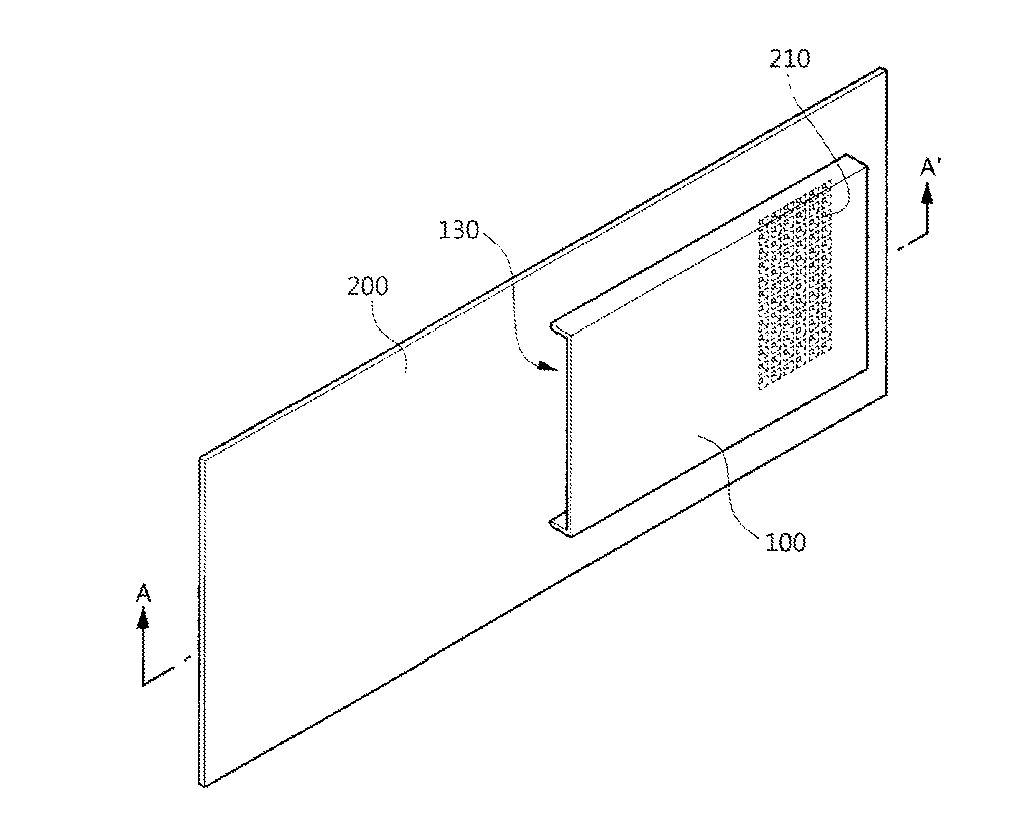
[0051]Referring to FIGS. 4 to 8, a vent structure for electromagnetic shielding in accordance with an embodiment of the present invention includes a conductive shielding case 200 having a vent 210 formed therein, a conductive shielding duct 100, and an EMI (Electro Magnetic Interference) gasket 300 installed at the bonding surface between the shielding case 200 and the shielding duct ...


PUM


Abstract

A vent structure for electromagnetic shielding includes: a conductive shielding case having a vent formed therein: a conductive shielding duct installed on the shielding case so as to cover the vent, including a space formed perpendicular to the direction of motion of air discharged from the vent to vent the air and a discharge port connected from the space to the outside to discharge the air introduced into the space to the outside, and shielding electromagnetic waves; and an EMI (Electro Magnetic Interference) gasket installed at a bonding surface between the shielding case and the shielding duct, and electrically connecting the shielding case and the shielding duct.

Description

CROSS-REFERENCE TO RELATED APPLICATION[0001]This application claims priority to Korean Patent Application No. 10-2012-0002054 filed on Jan. 6, 2012, which is incorporated herein by reference in its entirety.BACKGROUND OF THE INVENTION[0002]1. Field of the Invention[0003]Exemplary embodiments of the present invention relate to a vent structure for electromagnetic shielding; and, particularly, to a vent structure for electromagnetic shielding, which is conveniently mounted on a case of an electronic device, protects the electronic device by radiating heat generated inside the electronic device to the outside, and effectively attenuates electromagnetic waves generated inside the electronic device.[0004]2. Description of Related Art[0005]Electromagnetic waves are generated while an electromagnetic field, the intensity of which periodically changes, propagates in space.[0006]Recently, with the development of communication technology, various electronic devices, ranging from small-sized e...

Claims


Application Information

Patent Timeline
IPC IPC(8): H05K9/00
CPCH05K9/0041H05K7/20H05K9/00
Inventor KIM, UI-JUNGCHU, KWANG-UKKIM, JONG-KYULEE, DAE-HEON
Owner ELECTRONICS & TELECOMM RES INST
Learn More