Laser Drilling and Trepanning Device

a laser drilling and trepanning technology, applied in metal-working equipment, welding equipment, manufacturing tools, etc., can solve problems such as unplanned localized thermal deformation of workpieces

Active Publication Date: 2013-07-11
LUXCELIS TECH LLC
View PDF25 Cites 49 Cited by
  • Summary
  • Abstract
  • Description
  • Claims
  • Application Information

AI Technical Summary

Benefits of technology

[0010]The present invention provides laser drilling devices which are able to provide one or more of the foregoing desired improvements. In one aspect of the invention, there are provided laser drilling devices which include a laser beam source and a laser drilling head. The laser drilling head comprises a beam manipulator system in which the only dynamically moving optical element is a mirror. The mirror is dynamically and reciprocally translatable along the direction of the incoming laser beam and is also dynamically and reciprocally tiltable about an axis that is perpendicular to the nominal optical axis of the drilling head. The drilling head also includes a spinnable laser beam rotating system, a simplified compensation system, and a focusing system. The compensation system includes as its only laser beam path shifting optical elements one or two wedge plates which, if two, are fixably rotatable relative to one another in planes which are perpendicular to the nominal optical axis of the laser drilling device.

Problems solved by technology

Undesired localized thermal deformation of the workpiece may be caused by the heat input due to the irradiating of the workpiece with the laser beam.
Such deformation is especially a problem when the workpiece has poor thermal conductivity and a thin through thickness.
It is also a problem when the laser drilling or trepanning is being used to do very accurate machining of small features.

Method used


Image

  • Laser Drilling and Trepanning Device
  • Laser Drilling and Trepanning Device
  • Laser Drilling and Trepanning Device

Examples


Embodiment Construction

[0016]In this section, some preferred embodiments of the present invention are described in detail sufficient for one skilled in the art to practice the present invention. It is to be understood, however, that the fact that a limited number of preferred embodiments are described herein does not in any way limit the scope of the present invention as set forth in the appended claims. It is also to be understood that whenever a range of values is presented, the range is to be construed as disclosing its endpoints and every point therebetween as if each point was expressly described.

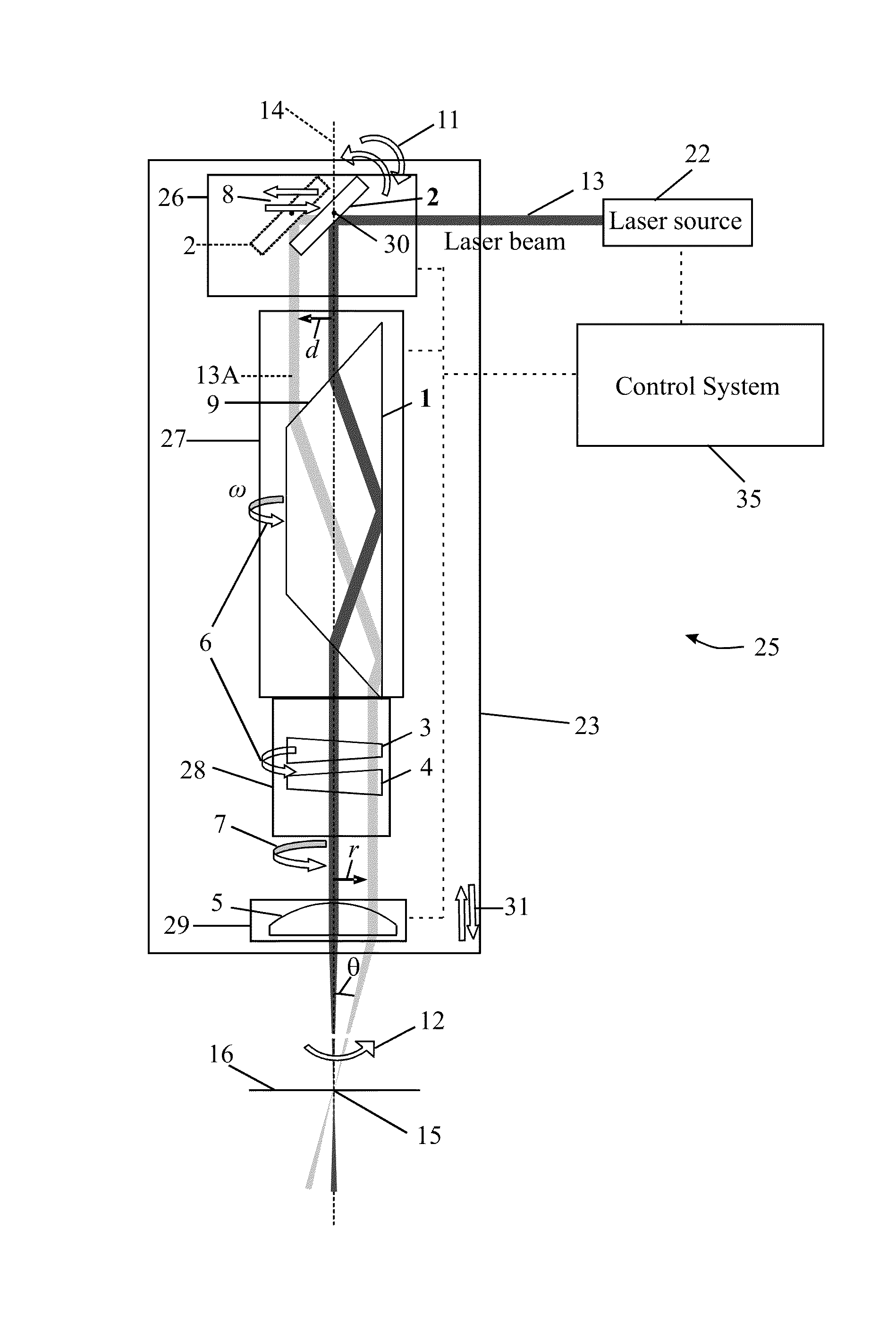
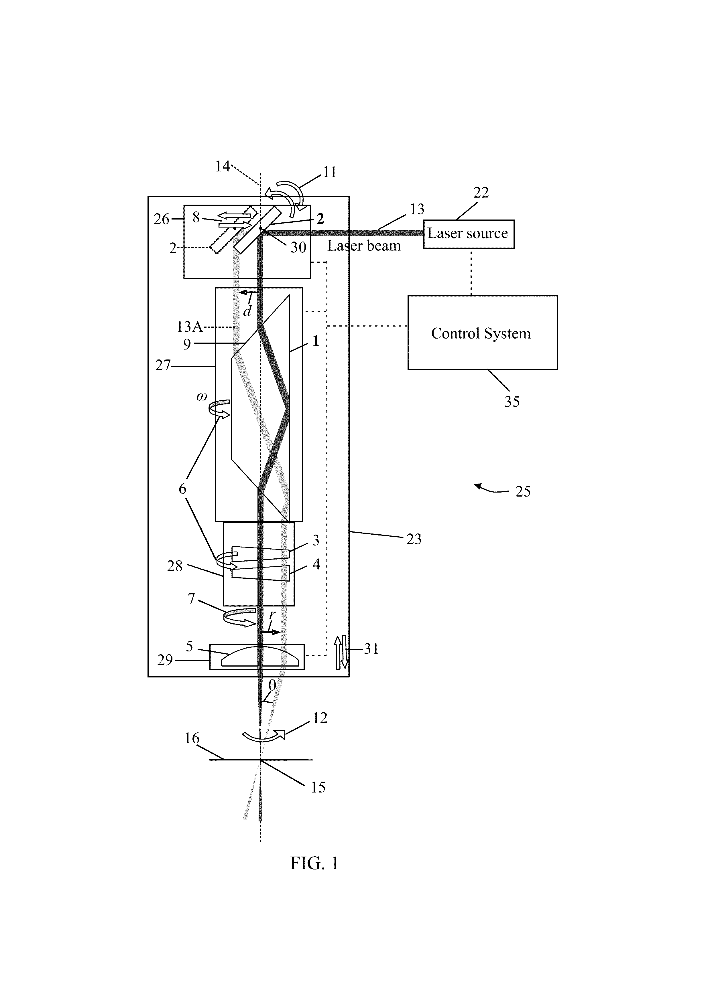
[0017]Referring to FIG. 1, there is shown a laser drilling device 25 according to an embodiment of the present invention. The laser drilling device 25 includes a laser source 22, which produces a laser beam 13, and a laser drilling head 23. The laser drilling head 23 comprises a laser beam manipulator system 26, a laser beam rotating system 27, a compensation system 28, and a focusing system 29. During opera...


PUM

PropertyMeasurementUnit
diametersaaaaaaaaaa
diameteraaaaaaaaaa
diameteraaaaaaaaaa

Abstract

Laser drilling devices are disclosed which include a laser beam source and a laser drilling head. The laser drilling head includes a beam manipulator system in which the only dynamically moving optical element is a mirror. The mirror is dynamically and reciprocally translatable along the direction of the incoming laser beam and is also dynamically and reciprocally tiltable about an axis that is perpendicular to the nominal optical axis of the drilling head. The drilling head also includes a spinnable laser beam rotating system, a simplified compensation system, and a focusing system. The compensation system includes as its only laser beam path shifting optical elements on or two wedge plates which, if two, are fixably rotatable relative to one another in planes which are perpendicular to the nominal optical axis of the laser drilling device.

Description

BACKGROUND[0001]1. Field of the invention[0002]The present invention relates to devices and methods for laser drilling and trepanning holes in workpieces.[0003]2. Background of the Invention[0004]In laser machining, a laser beam generation device is used in conjunction with an optical system to direct the laser beam onto a workpiece that is to be machined. The impingement of the laser beam on the workpiece locally melts and / or vaporizes the workpiece material to produce or extend a hole or cut in the workpiece. The location of the laser beam impingement point on the workpiece may be controlled by moving one or both of the laser beam and the workpiece relative to one another to thereby control the geometry of the hole or cut.[0005]In laser drilling, a hole, which can be through or blind, is formed in a workpiece by directing the laser beam at a preselected spot on the workpiece. The focus point of the beam may be adjusted during the drilling to correlate with the current depth of the...

Claims


Application Information

Patent Timeline
Patent Type & Authority Applications(United States)
IPC IPC(8): B23K26/38
CPCB23K26/0643B23K26/386B23K26/381B23K26/0652B23K26/382B23K26/389
Inventor WANG, WEIMIN
Owner LUXCELIS TECH LLC
Why Eureka
Try Eureka