Wireless power supply system for lighting and lighting apparatus

Active Publication Date: 2013-07-11
PANASONIC CORP
View PDF4 Cites 36 Cited by
  • Summary
  • Abstract
  • Description
  • Claims
  • Application Information

AI Technical Summary

Benefits of technology

[0023]According to the present invention, it is enabled to stabilize the supply power to a lighting load regardless of the fluctuation of the outpu

Problems solved by technology

In the conventional wireless power supply system, it is possible that supply power to the lighting load becomes unstable, because an output voltage of the power reception coil varies due to: a load change caused by a temperature character, an age-related deterioration or the like; a relative position gap (misalignment) between the power transmission unit (power transmission coil) and the power reception unit (power reception coil); a

Method used


Image

  • Wireless power supply system for lighting and lighting apparatus
  • Wireless power supply system for lighting and lighting apparatus
  • Wireless power supply system for lighting and lighting apparatus

Examples


Example

First Embodiment

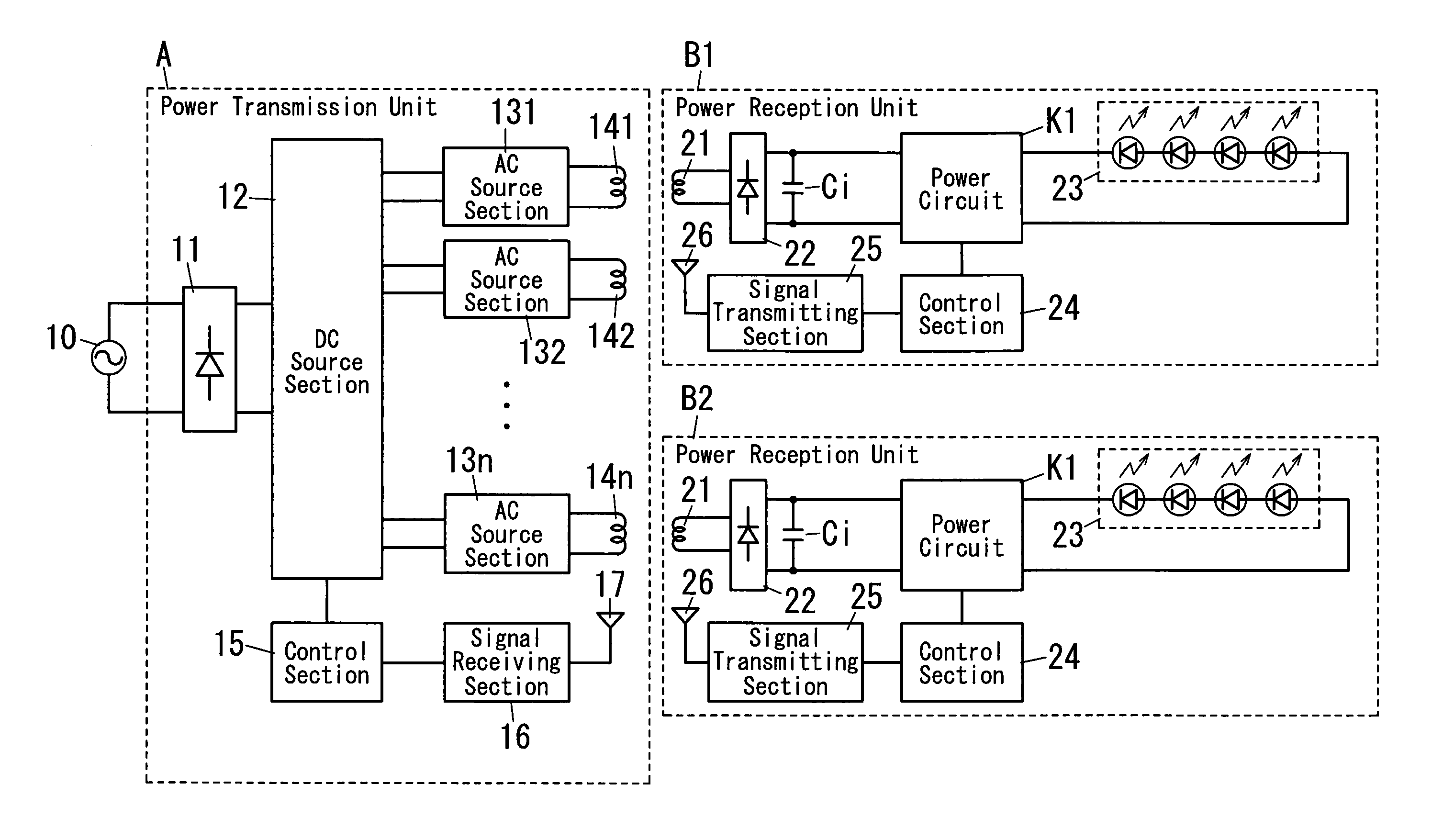
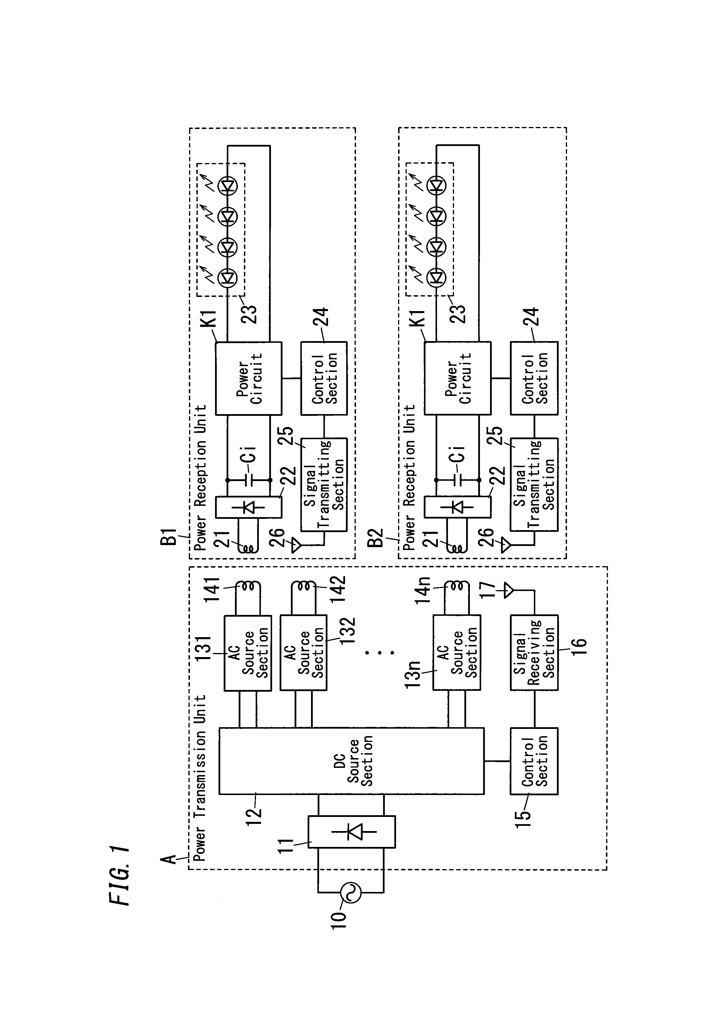
[0038]A circuit configuration according to a wireless power supply system (contactless power supply system) for lighting of this embodiment is shown in FIG. 1.

[0039]The present system includes one power transmission unit A and one or more of power reception units B (B1, B2 . . . Bn). The system exemplified in FIG. 1 includes one power transmission unit A and two power reception units (B1, B2). Hereinafter, when not particularly specified, the power reception unit is denoted by a sign “B”. Here, the power reception unit B is provided separately from the power transmission unit A.

[0040]The power transmission unit A includes a rectification section 11, a DC source section 12, AC source sections (131˜13n), power transmission coils (141˜14n), a control section (transmission-side control section) 15, a signal receiving section 16, and an antenna 17. Hereinafter, when not particularly specified, the AC source section is denoted by a sign “13”. Hereinafter, when not particul...

Example

Second Embodiment

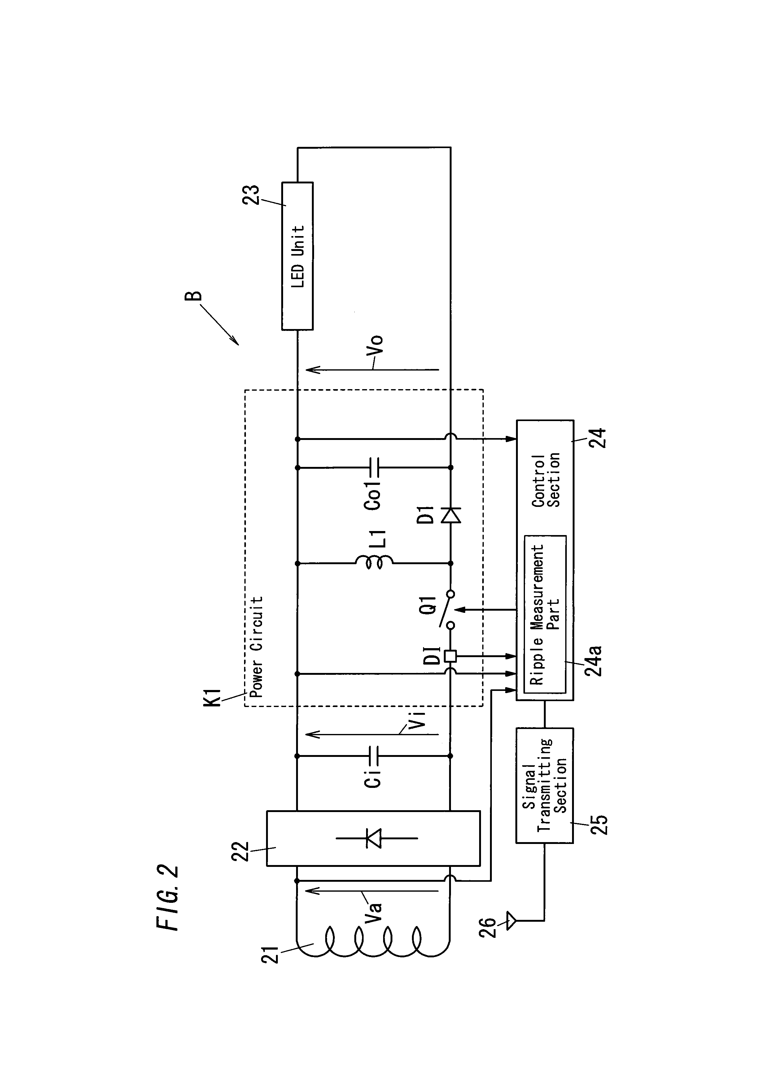
[0109]The wireless power supply system for lighting of this embodiment includes the same power transmission unit A with that in the first embodiment, and configuration of the power reception unit B is different. A circuit configuration of the power reception unit B of this embodiment is shown in FIG. 5. Note that, like kind elements are assigned the same reference signs as depicted in the first embodiment, and are not explained in detail.

[0110]The power reception unit B is provided with a charge-discharge circuit 27 between the input capacitor Ci and the power circuit K1. A battery 28 is connected to the charge-discharge circuit 27.

[0111]The charge-discharge circuit 27 has: a charging function of charging the battery 28 using the electric power of the power reception coil 21; and a discharging function of discharging the stored power in the battery 28 to the power circuit K1. As a result, the charge-discharge circuit 27 can supply an electric power from the battery ...

Example

Third Embodiment

[0114]The wireless power supply system for lighting of this embodiment includes the same power transmission unit A with that in the first embodiment, and configuration of power circuit of the power reception unit B is different. Circuit configurations of the power circuits (K2˜K5) of the power reception unit B of this embodiment are shown in FIGS. 6 to 9. Note that, like kind elements are assigned the same reference signs as depicted in the first embodiment, and are not explained in detail.

[0115]The power circuit K2 shown in FIG. 6 is composed of a Buck-Boost chopper circuit having two switching devices.

[0116]In the power circuit K2, a series circuit of a switching device Q11 and a diode D11 is provided between both ends of the input capacitor Ci, where the switching device Q11 is connected to the positive electrode side of the input capacitor Ci and an anode of the diode D11 is connected to the negative electrode side of the input capacitor Ci. A series circuit of a...


PUM


Abstract

A wireless power supply system for lighting includes: a power transmission unit including a power transmission coil; and a power reception unit including a power reception coil. The power transmission coil generates an AC magnetic field in response to a supplied AC power. The power reception coil receives an electric power from the power transmission unit through an electromagnetic induction due to the AC magnetic field generated by the power transmission coil. The power reception unit further includes a power circuit and a receive-side control section. The power circuit receives an output power from the power reception coil and to perform Buck-Boost operation so as to output a predetermined electric power to a lighting load. The receive-side control section controls the Buck-Boost operation of the power circuit. The power circuit is configured to be capable of boosting and stepping-down of the output power from said power reception coil.

Description

TECHNICAL FIELD[0001]This invention relates to a wireless power supply system for lighting and a lighting apparatus.BACKGROUND ART[0002]For example, Japanese patent No. 2853207 (hereinafter referred to as document 1), Japanese patent application publication No. 2011-50163A (hereinafter referred to as document 2), and Japanese patent application publication No. 2011-29067A (hereinafter referred to as document 3) disclose wireless power supply systems (contactless power supply systems) configured to supply a lighting load with electric power in a non-contact manner. Such a wireless power supply system includes a power transmission unit and a power reception unit. The power transmission unit includes a power transmission coil to which an AC power is supplied. The power reception unit includes a power reception coil which receives an electric power from the power transmission unit through an electromagnetic induction due to an AC magnetic field generated by the power transmission coil i...

Claims


Application Information

Patent Timeline
IPC IPC(8): H05B37/02H02M3/155H02M3/28H05B44/00
CPCH05B37/02H02J17/00H02J5/005H05B47/10H05B45/3725H05B45/10H05B44/00H02J50/402H02J50/90H02J50/80H02J50/10
Inventor NAKAJO, AKIRACHAWALARAT, NADDAKIDO, HIROSHI
Owner PANASONIC CORP
Why Eureka
Try Eureka