Light source module and projection apparatus

Active Publication Date: 2013-07-11
CORETRONIC
View PDF6 Cites 36 Cited by
  • Summary
  • Abstract
  • Description
  • Claims
  • Application Information

AI Technical Summary

Benefits of technology

[0014]According to the above descriptions, the invention has at least one of following advantages. In embodiment of the invention, by configuring the wavelength conversion area and the polarization conversion area in the wavelength conversion device, and in collaboration with usage of the polarization and color separation unit, the converted color beam and the excit

Problems solved by technology

However, since the light-emitting efficiency of an LED has limitation, some technicians use a mixed

Method used


Image

  • Light source module and projection apparatus
  • Light source module and projection apparatus
  • Light source module and projection apparatus

Examples


Example

First Embodiment

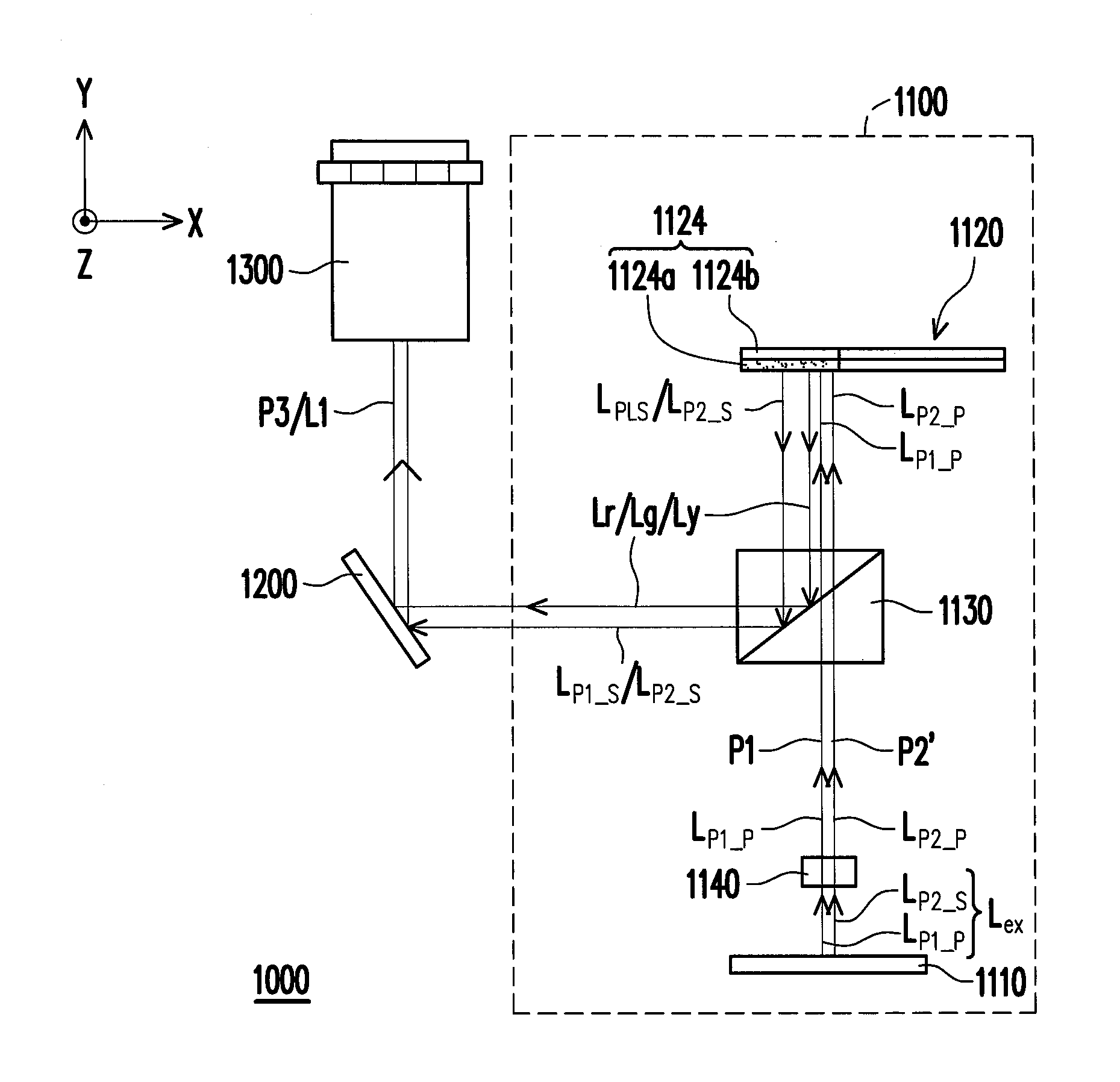
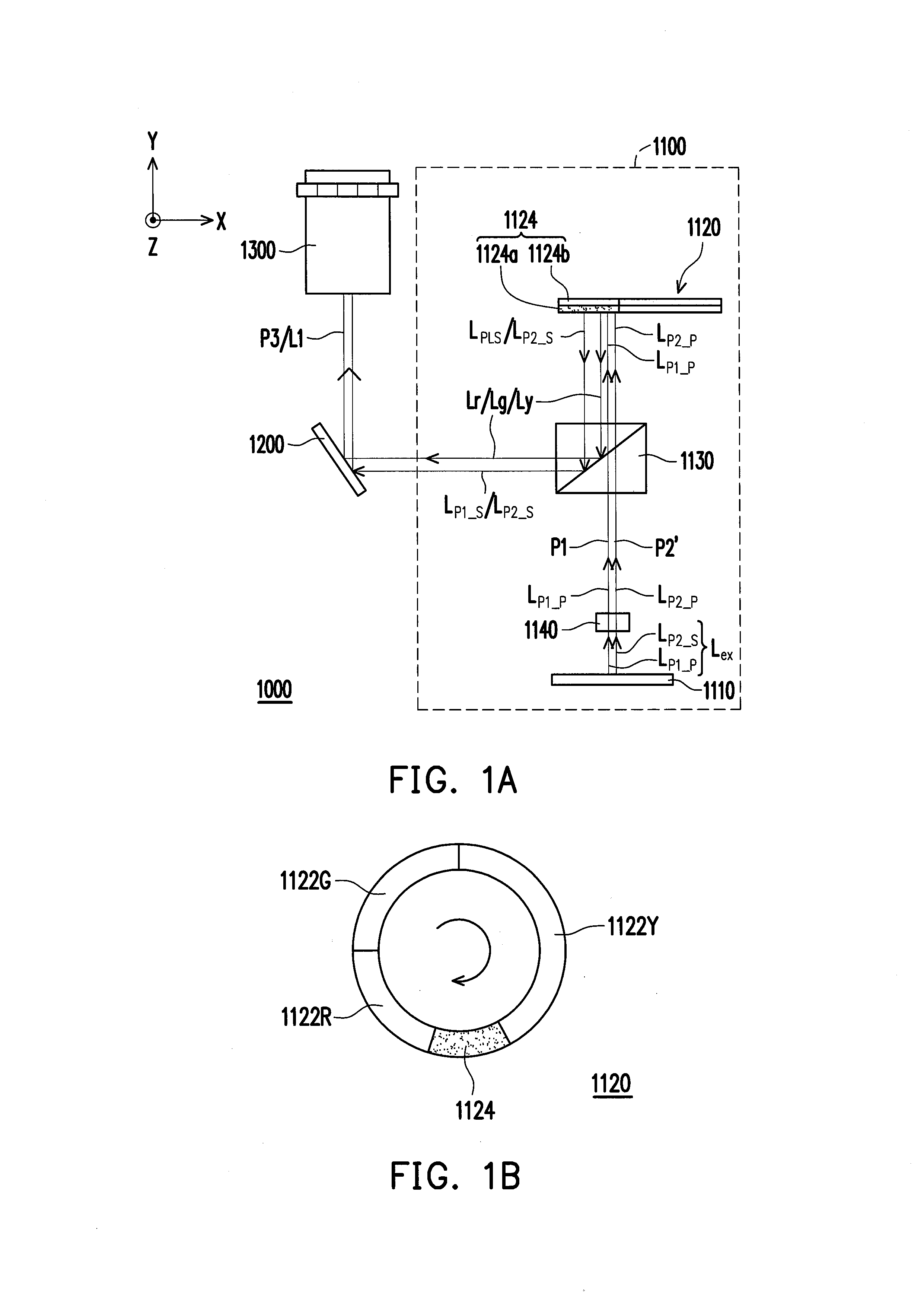
[0025]FIG. 1A is a top view of a projection apparatus according to the first embodiment of the invention. Referring to FIG. 1A, the projection apparatus 1000 of the embodiment includes a light source module 1100, a light valve 1200 and a projection lens 1300. The light source module 1100 includes a light-emitting device 1110, a wavelength conversion device 1120 and a polarization and color separation unit 1130. The light-emitting device 1110 is used to provide an excitation beam Lex. The excitation beam Lex includes a first portion beam LP1—Pand a second portion beam LP2—S, wherein the first portion beam LP1—P has a first polarization direction, and the second portion beam LP2—S has a second polarization direction. However, the excitation beam Lex is not limited to only include the first portion beam LP1—P having the first polarization direction and the second portion beam LP2—S having the second polarization direction. In other words, the excitation beam Lex may als...

Example

Second Embodiment

[0046]FIG. 2 is a top view of a projection apparatus 2000 according to a second embodiment of the invention. The projection apparatus 2000 of FIG. 2 is similar to the projection apparatus 1000 of FIG. 1A, and a difference therebetween is that a light source module 2100 of FIG. 2 further includes a quarter-wave plate 2120, and the light source module 2100 of FIG. 2 does not have the polarization conversion system 1140 of FIG. 1A.

[0047]As shown in FIG. 2, the polarization and color separation unit 1130 is disposed between the light-emitting device 1110 and the quarter-wave plate 2120. The polarization and color separation unit 1130 reflects the second portion beam LP2—S with the second polarization direction to the quarter-wave plate 2120, and the quarter-wave plate 2120 converts the second polarization direction (for example, the S-polarization) of the second portion beam LP2—S to the first polarization direction (for example, the P-polarization).

[0048]Besides, the l...

Example

Third Embodiment

[0052]FIG. 3A is a top view of a projection apparatus according to a third embodiment of the invention. The projection apparatus 3000 of FIG. 3A is similar to the projection apparatus 2000 of FIG. 2, and a difference therebetween is that the light source module of the projection apparatus 3000 further includes a quarter-wave plate 3120 and a polarization conversion device 3130.

[0053]FIG. 3B is a top view of the quarter-wave plate 3120 and the polarization conversion device 3130 of FIG. 3A viewed along an X-direction. Referring to FIG. 3A and FIG. 3B, the polarization conversion device 3130 of the embodiment is capable of rotating, which is, for example, a color wheel. The quarter-wave plate 3120 is disposed on the polarization conversion device 3130. In detail, the light source module 3100 further includes a reflection unit 3140, and the quarter-wave plate 3120 is disposed on the reflection unit 3140. In detail, when the second portion beam LP2—S with the second pola...


PUM


Abstract

A light source module includes a light-emitting device, a wavelength conversion device and a polarization and color separation unit. The light-emitting device provides an excitation beam including a first portion beam having a first polarization direction. The wavelength conversion device includes a first wavelength conversion area and a polarization conversion area. When the first portion beam irradiates the first wavelength conversion area, the first portion beam is converted into a first color beam. When the first portion beam irradiates the polarization conversion area, the first polarization direction of the first portion beam is converted to a second polarization direction. The polarization and color separation unit is disposed between the wavelength conversion device and the light-emitting device, and transmits the first portion beam with the first polarization direction, and reflects the first portion beam with the second polarization direction and the first color beam to the same direction.

Description

CROSS-REFERENCE TO RELATED APPLICATION[0001]This application claims the priority benefit of China application serial no. 201210007006.2, filed on Jan. 11, 2012. The entirety of the above-mentioned patent application is hereby incorporated by reference herein and made a part of this specification.BACKGROUND OF THE INVENTION[0002]1. Field of the Invention[0003]The invention relates to an optical device. Particularly, the invention relates to a light source module and a projection apparatus.[0004]2. Description of Related Art[0005]With development of display technology, in a projection apparatus, besides that an ultra high pressure lamp (UHP lamp) suitable for emitting a white light can be used together with a color wheel to sequentially generate a red light, a green light and a blue light, so that the projection apparatus can provide color images. In recent years, the projection apparatus using light-emitting diodes (LEDs) as light sources is further developed. However, since the ligh...

Claims


Application Information

Patent Timeline
IPC IPC(8): G03B21/14F21V9/14
CPCG03B21/204G03B21/2073G02B27/286G02B26/008G02B27/1033G03B33/08G02B27/283H04N9/3167H04N9/3197
Inventor WEI, CHING-CHUANCHEN, SHU-MINCHIU, HAO-WEICHEN, KO-SHUN
Owner CORETRONIC
Why Eureka
Try Eureka