Apparatus and method for transmitting data using multiple antennas and beamforming

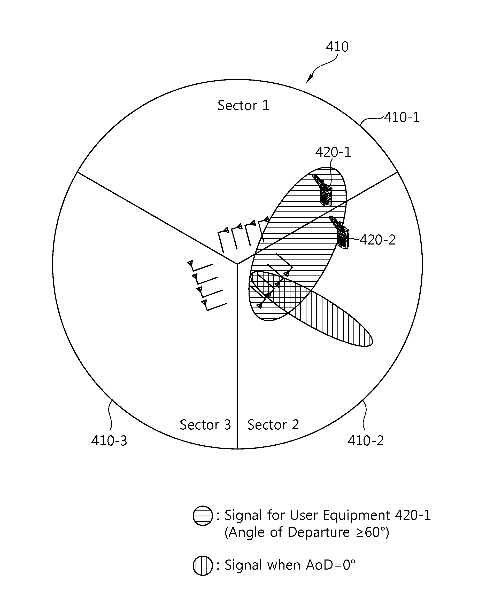
a technology of antennas and beamforming devices, applied in diversity/multi-antenna systems, amplitude demodulation, high-level techniques, etc., can solve the problems of reducing the power of reception signals, affecting the performance of user equipment closer to the cell edge, and affecting the interference of user equipment placed in another cell, so as to prevent the effect of power loss due to angular spread and constant beam width

Active Publication Date: 2013-07-11
PANTECH CORP
View PDF11 Cites 15 Cited by
  • Summary
  • Abstract
  • Description
  • Claims
  • Application Information

AI Technical Summary

Benefits of technology

[0013]Yet another object of the present invention is to provide a beamforming method of regularly maintaining a beam width.
[0026]A constant beam width can be supported irrespective of an Angle of Departure, a power loss due to an angular spread can be prevented, and the occurrence of a shadow area in a is great angle of departure can be solved.

Problems solved by technology

In general, in a multi-cellular communication system, if communication between a base station and user equipment is performed in the state in which a frequency reuse factor ‘1’ is maintained in the same time and frequency band in each cell by not taking other cells into consideration, the performance of user equipment closer to a cell edge is greatly deteriorated owing to the distortion of a reception signal resulting from a reduction in the power of the reception signal and interference from other cells.
This method, however, can give interference to user equipment placed in another cell.
If the number of transmission antennas is increased in order to remove this interference, there is a problem in that a power loss is generated because a beam width (beam width) is narrowed.

Method used


Image

  • Apparatus and method for transmitting data using multiple antennas and beamforming
  • Apparatus and method for transmitting data using multiple antennas and beamforming
  • Apparatus and method for transmitting data using multiple antennas and beamforming

Examples


Embodiment Construction

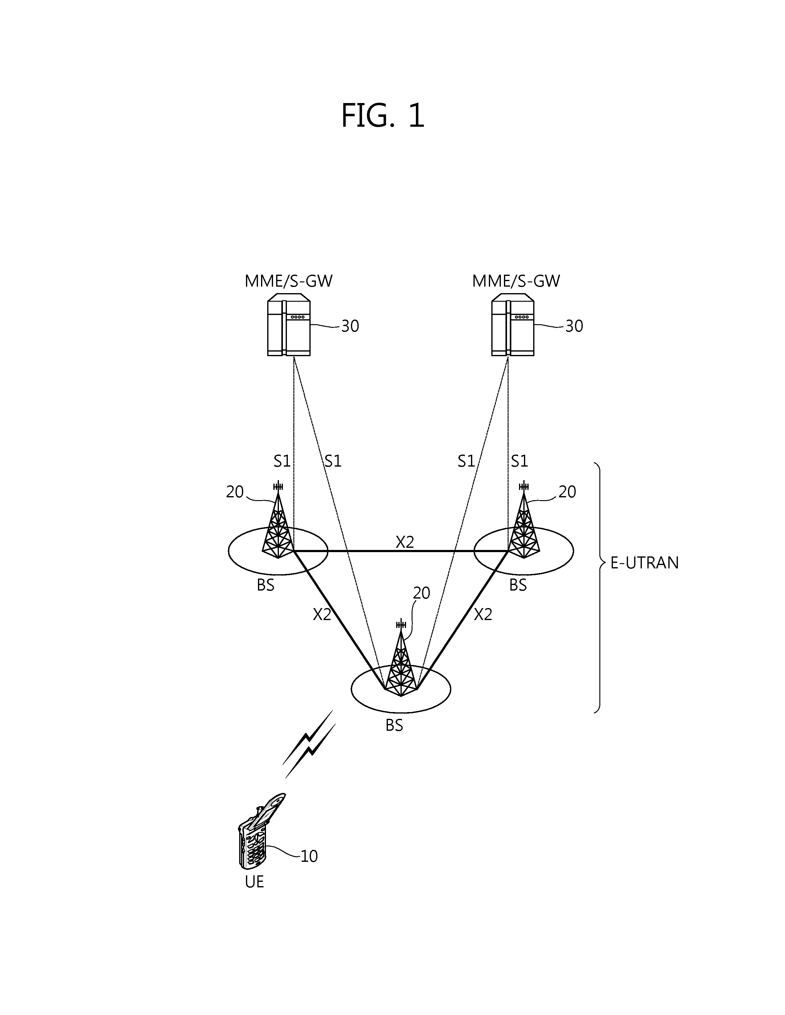
[0044]The following technologies can be used in a variety of wireless communication systems, such as Code Division Multiple Access (CDMA), Frequency Division Multiple Access (FDMA), Time Division Multiple Access (TDMA), Orthogonal Frequency Division Multiple Access (OFDMA), and Single Carrier Frequency Division Multiple Access (SC-FDMA). CDMA can be implemented by radio technology, such as Universal Terrestrial Radio Access (UTRA) or CDMA2000. TDMA can be implemented by radio technology, such as Global is System for Mobile communications (GSM) / General Packet Radio Service (GPRS) / Enhanced Data Rates for GSM Evolution (EDGE). OFDMA can be implemented by radio technology, such as IEEE 802.11 (Wi-Fi), IEEE 802.16 (WiMAX), IEEE 802.20, or Evolved UTRA (E-UTRA). UTRA is part of a Universal Mobile Telecommunications System (UMTS). 3rd Generation Partnership Project (3GPP) Long Term Evolution (LTE) is part of an Evolved UMTS (E-UMTS) using E-UTRA, and 3GPP LTE adopts OFDMA in downlink and a...


PUM


Abstract

Provided are an apparatus and method for transmitting data using multiple antennas and beamforming. The apparatus of the present invention comprises: a modulation unit which performs constellation mapping on input bits to generate modulated symbols; a pre-coding unit which multiplies a pre-coding matrix and the modulated symbols to generate pre-coded symbols; and a plurality of transmitting antennas for transmitting the pre-coded symbols. According to the present invention, a beam width is maintained constant, regardless of a radiation angle, thus preventing a loss of power caused by an angular spread and preventing the generation of shadow zone at a large radiation angle.

Description

CROSS-REFERENCE TO RELATED APPLICATIONS[0001]This application is the National Stage Entry of International Application No. PCT / KR2011 / 006809, filed on Sep. 15, 2011, and claims priority from and the benefit of Korean Patent Application No. 10-2010-0092125, filed on Sep. 17, 2010, both of which are hereby incorporated by reference for all purposes as if fully set forth herein.BACKGROUND[0002]1. Field[0003]The present invention relates to wireless communication and, more particularly, to a method and apparatus for transmitting data using multiple antennas and beamforming.[0004]2. Discussion of the Background[0005]In general, in a multi-cellular communication system, if communication between a base station and user equipment is performed in the state in which a frequency reuse factor ‘1’ is maintained in the same time and frequency band in each cell by not taking other cells into consideration, the performance of user equipment closer to a cell edge is greatly deteriorated owing to the...

Claims


Application Information

Patent Timeline
Patent Type & Authority Applications(United States)
IPC IPC(8): H04B7/06
CPCH04B7/0639H04B7/0691H04B7/0617H04B7/06Y02D30/70
Inventor PARK, KYOUNG MIN
Owner PANTECH CORP
Why Eureka
Try Eureka