Image processing apparatus, imaging apparatus, and image processing method

a technology of image processing and imaging apparatus, applied in the field of estimating a point spread function, can solve the problems of reduced capture image quality, increased noise in captured images, and reduced light reception amount per, and achieve the effect of improving psf estimation accuracy

Inactive Publication Date: 2013-07-11
SOVEREIGN PEAK VENTURES LLC
View PDF3 Cites 12 Cited by
  • Summary
  • Abstract
  • Description
  • Claims
  • Application Information

AI Technical Summary

Benefits of technology

[0014]With an image processing apparatus according to an aspect of the present invention, the PSF estimation accuracy can be improved.

Problems solved by technology

However, the large number of pixels reduces the light reception amount per pixel, with the result that noise in the captured images has increased.
However, when the exposure time is longer, camera shake blur and motion blur are easier to take place and the quality of the capture images is reduced.

Method used


Image

  • Image processing apparatus, imaging apparatus, and image processing method
  • Image processing apparatus, imaging apparatus, and image processing method
  • Image processing apparatus, imaging apparatus, and image processing method

Examples


embodiment 1

[0072]The following will describe an imaging apparatus according to Embodiment 1 with reference to the drawings.

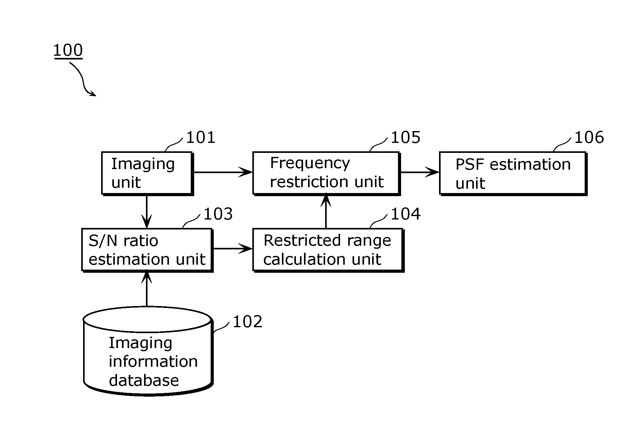
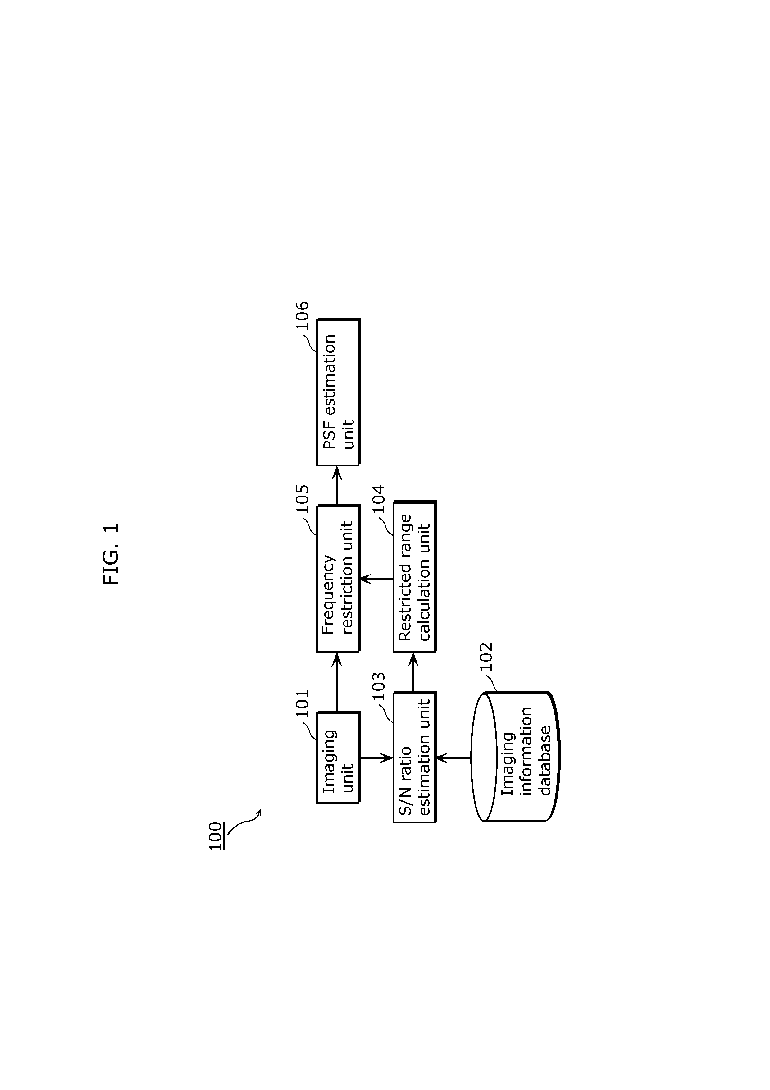
[0073]FIG. 1 is a block diagram of an imaging apparatus 100 according to Embodiment 1. As shown in FIG. 1, the imaging apparatus 100 includes an imaging unit 101, an imaging information database 102, an S / N ratio estimation unit 103, a restricted range calculation unit 104, a frequency restriction unit 105, and a PSF estimation unit 106. In the present embodiment, the imaging apparatus 100 estimates the PSF of an input image captured by the imaging unit 101. The following will describe each of the structural elements of the imaging apparatus 100 according to the present embodiment with reference to FIG. 1.

[0074]The imaging unit 101 generates image data (input image) by converting an optical image of the object into a digital signal. Then, the imaging unit 101 outputs the input image to the S / N ratio estimation unit 103 and the frequency restriction unit 105.

[0075]The imagi...

embodiment 2

[0134]The following will describe Embodiment 2 with reference to the drawings.

[0135]FIG. 8 is a diagram showing a configuration of an imaging apparatus 200 according to Embodiment 2. It should be noted that the same reference numbers are used for the same elements as the imaging apparatus according to Embodiment 1. A detailed description thereof will be omitted. The imaging apparatus 200 according to Embodiment 2 includes a distance estimation unit 207 in addition to the structural elements in Embodiment 1. The imaging apparatus 200 according to the present embodiment estimates distance information of captured scenes using PSFs estimated from a plurality of input images captured by the imaging unit 101. The following will describe each of the structural elements of the imaging apparatus 200 according to the present embodiment with reference to FIG. 8.

[0136]An imaging unit 101, an imaging information database 102, an S / N ratio estimation unit 103, a restricted range calculation unit ...

embodiment 3

[0143]The following will describe Embodiment 3 in detail with reference to the drawings.

[0144]FIG. 9 is a diagram showing a configuration of an imaging apparatus 300 according to Embodiment 3. It should be noted that the same reference numbers are used for the same elements as in the imaging apparatus according to Embodiments 1 and 2, and a detailed description thereof will be omitted. The imaging apparatus 300 according to Embodiment 3 includes a distance information database 308 in addition to the structural elements in Embodiment 2. The imaging apparatus 300 according to the present embodiment estimates distance information of captured scenes using PSFs estimated from a plurality of input images captured by the imaging unit 101. The following will describe each of the structural elements of the imaging apparatus 300 according to the present embodiment with reference to FIG. 9.

[0145]An imaging unit 101, an imaging information database 102, an S / N ratio estimation unit 103, a frequ...


PUM


Abstract

An image processing apparatus which estimates a point spread function (PSF) of at least one input image, and the image processing apparatus includes: an S / N ratio estimation unit which estimates an S / N ratio of the input image at each spatial frequency; a restricted range calculation unit which calculates a restricted range that is a range of the spatial frequency in which the frequency component of the input images are restricted and that more likely includes a spatial frequency in which the S / N ratio is lower; a frequency restriction unit which generates a restricted image by restricting a frequency component of the input image within the restricted range; and a PSF estimation unit which estimates the PSF of the input image, using the restricted image

Description

TECHNICAL FIELD[0001]The present invention relates to a technique for estimating a Point Spread Function (PSF) in an input image.BACKGROUND ART[0002]In recent years, the total number of pixels in an imaging element included in a digital still camera and a digital video camera has been increasing rapidly, and the resolution of captured images has been improved. However, the large number of pixels reduces the light reception amount per pixel, with the result that noise in the captured images has increased.[0003]The extension of exposure time is effective for suppressing the noise. However, when the exposure time is longer, camera shake blur and motion blur are easier to take place and the quality of the capture images is reduced.[0004]Therefore, a technique has been proposed for removing camera shake blur and motion blur from a captured image with reduced quality (refer to Patent Literature 1 and Non Patent Literature 1). In the methods according to Patent Literature 1 and Non Patent ...

Claims


Application Information

Patent Timeline
Patent Type & Authority Applications(United States)
IPC IPC(8): G06T7/00
CPCH04N1/4092G06T7/00H04N5/23267G06T2207/20201G06T5/10G06T7/0069G06T2207/20056G06T5/003G06T7/571H04N23/683
Inventor FUJII, TAKASHIMONOBE, YUSUKE
Owner SOVEREIGN PEAK VENTURES LLC
Why Eureka
Try Eureka