System and Method for Tissue Ablation in a Body Cavity

a tissue ablation and body cavity technology, applied in the field of body cavity tissue ablation systems and methods, can solve the problems of difficult for a physician to find out, too much or too little tissue may be ablated during an ablation procedure,

Active Publication Date: 2013-07-11
HOLOGIC INC
View PDF18 Cites 11 Cited by
  • Summary
  • Abstract
  • Description
  • Claims
  • Application Information

AI Technical Summary

Benefits of technology

[0007]In some embodiments, at least two ultrasonic transducers may be coupled to the outer surface of the substrate and positioned in opposing lateral regions of the substrate. At least two ultrasonic transducers may be coupled to the outer surface of the substrate, one positioned in the lateral region and one positioned in a medial region of the substrate. The system and method may further include a suction device fluidly coupled to the ablation device. The substrate may be an electrode carrier and the energy transport elements may be electrodes. The energy source may be a radiofrequency source, a microwave source, and / or an ultrasound source. Alternatively, or in addition, the energy source may be a fluid having a temperature of greater than about 45° C. At least a portion of the substrate may include a metallized fabric. The ultrasonic transducers may include a single element ultrasonic transducer. The system and method may further include one or more sensors positioned near the lateral region of the substrate and configured to sense a force applied to the outer surface of the substrate. The system and method may further include a spring coupled to the outer surface of the substrate and the ultrasonic transducer coupled to the spring. The system and method may further include a processor coupled to the ultrasonic transducer and coupled to the energy source. The processor may be configured to receive information from the ultrasonic transducer in order to determine a parameter and may be configured to terminate power to the energy source based on the parameter. The parameter may include ablation depth, time, temperature, tissue impedance, and / or total energy.
[0008]In accordance with another embodiment of the invention, a uterine cavity measurement device includes a uterine length measurement device having an elongate tube that includes a distal end, a proximal end, a hollow interior, and a slot extending longitudinally along its proximal end, and an elongate shaft that includes a distal end and a proximal end, and is configured to move within the hollow interior of the elongate tube. The uterine cavity measurement device also includes a control knob coupled to the elongate shaft and configured to move the elongate shaft within the elongate tube when the control knob moves along a length of the slot. The distal end of the elongate shaft is configured to protrude from the distal end of the elongate tube. The uterine cavity measurement device also includes at least one ultrasonic transducer positioned near the distal end of the elongate shaft and a spring coupled to the distal end of the elongate shaft and coupled to the at least one ultrasonic transducer.
[0009]In accordance with another embodiment of the invention, a uterine cavity measurement device includes a uterine length measurement device having an elongate tube that includes a distal end, a proximal end, a hollow interior, and a slot extending longitudinally along its proximal end, and an elongate shaft that includes a distal end and a proximal end, and is configured to move within the hollow interior of the elongate tube. The uterine cavity measurement device also includes a control knob configured to move the elongate shaft within the elongate tube when the control knob moves along a length of the slot. The distal end of the elongate shaft is configured to protrude from the distal end of the elongate tube. The uterine cavity measurement device also includes at least one ultrasonic transducer coupled to the distal end of the elongate shaft and a spring coupled to the proximal end of the elongate shaft and coupled to the control knob.

Problems solved by technology

These ablation procedures, however, are often carried out without direct endoscopic visualization.
Consequently, the ablation depth and ablation profile are usually done by assumption since little data are available to help guide the physician as to how deep the tissue ablation needs to go.
It is also difficult for a physician to find out when ablation has been carried out to a desired depth within the tissue during the procedure.
Thus, in some instances, too much or too little tissue may be ablated during an ablation procedure.

Method used


Image

  • System and Method for Tissue Ablation in a Body Cavity
  • System and Method for Tissue Ablation in a Body Cavity
  • System and Method for Tissue Ablation in a Body Cavity

Examples


Embodiment Construction

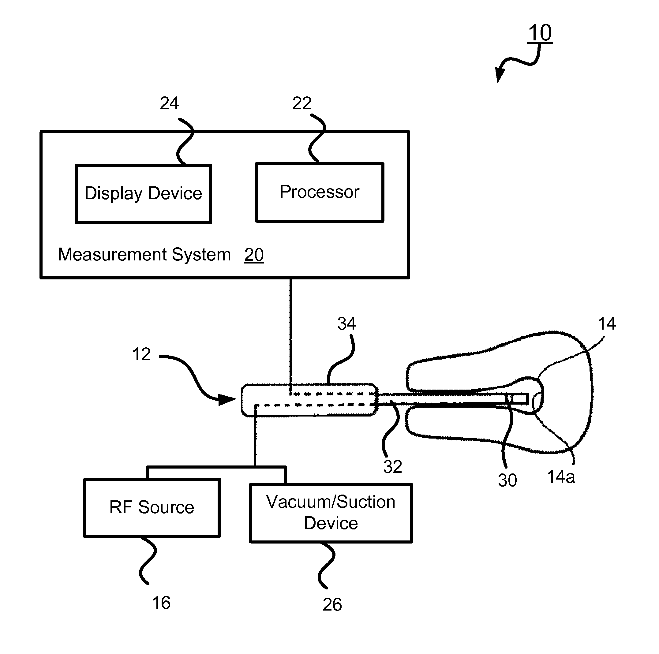
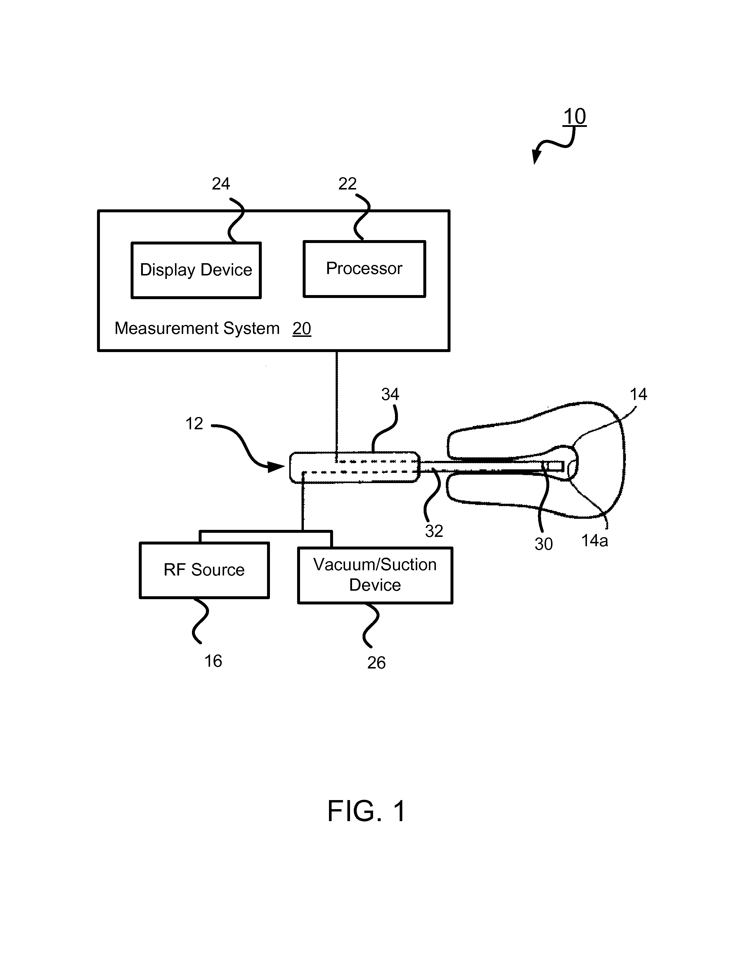
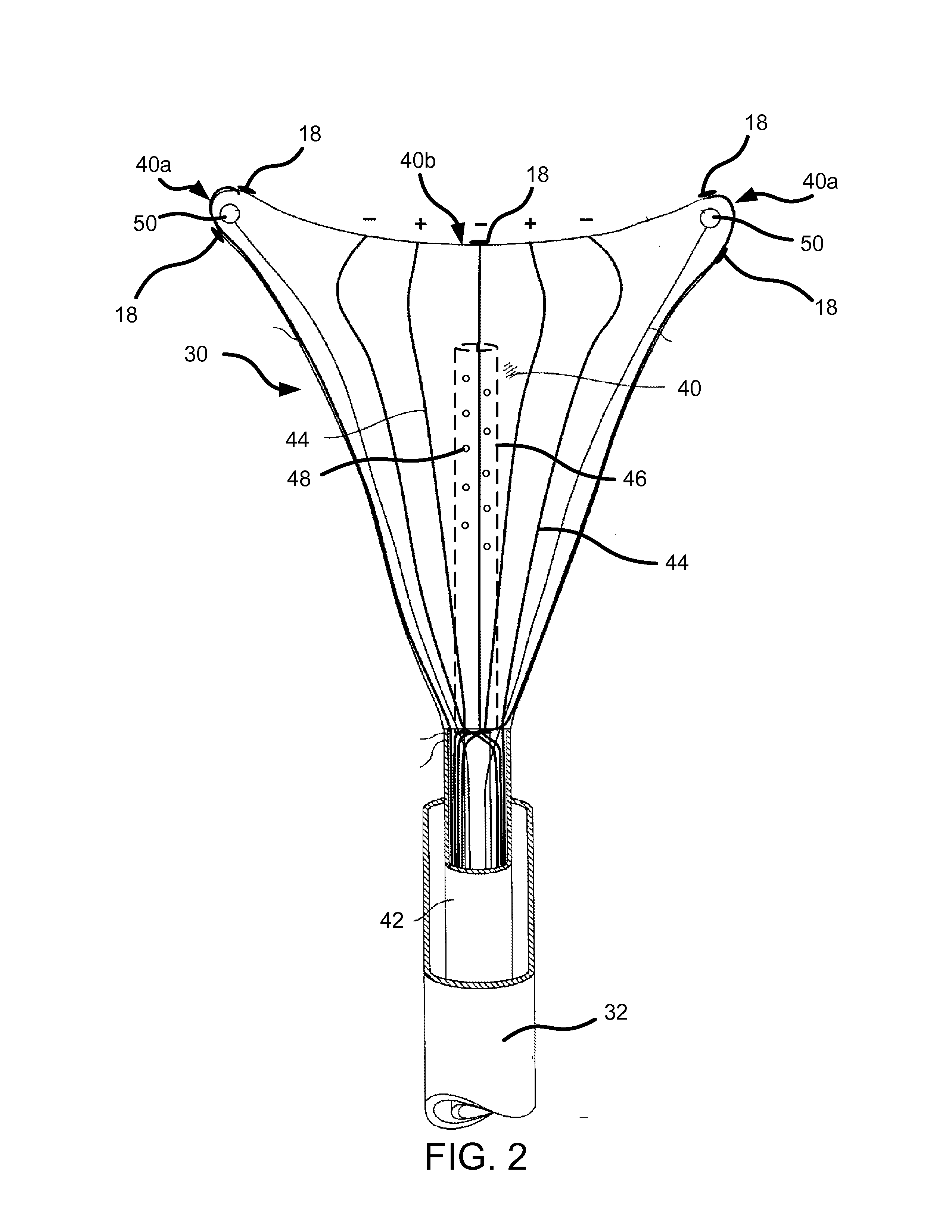
[0004]In accordance with one embodiment of the invention, a tissue ablation system includes an ablation device having a substrate with an outer surface and energy transport elements coupled to the outer surface of the substrate. The substrate is configured to have a shape that approximates an interior shape of a uterus. The system further includes an energy source electrically coupled to the energy transport elements and at least one ultrasonic transducer positioned in a lateral region of the uterus.

[0005]In accordance with another embodiment of the invention, a method of forming a tissue ablation system includes providing an ablation device having a substrate with an outer surface and energy transport elements coupled to the outer surface of the substrate. The substrate is configured to have a shape that approximates an interior shape of a uterus. The method further includes electrically coupling an energy source to the energy transport elements and coupling the at least one ultras...


PUM


Abstract

A tissue ablation system and method of forming same includes an ablation device having a substrate with an outer surface and energy transport elements coupled to the outer surface. The substrate is configured to have a shape that approximates an interior shape of a uterus. The system and method further including an energy source electrically coupled to the energy transport elements and at least one ultrasonic transducer positioned in a lateral region of the uterus.

Description

TECHNICAL FIELD[0001]The present invention generally relates to systems and methods for tissue ablation in a body cavity and, more particularly, the invention relates to a tissue ablation system and method that measures the wall thickness of the body cavity prior to and / or during the ablation procedure.BACKGROUND ART[0002]Ablation of the interior lining of a body organ is a procedure which involves heating the organ lining to temperatures which destroy the cells of the lining, coagulate blood and / or denature tissue proteins. Existing methods for the energy transfer as part of effecting ablation include circulation of heated fluid inside the organ (either directly or inside a balloon), laser treatment of the organ lining, microwave heating of the tissue, high power ultrasound heating of the tissue or resistive heating using application of radiofrequency (RF) energy to the tissue to be ablated. These ablation procedures, however, are often carried out without direct endoscopic visuali...

Claims


Application Information

Patent Timeline
Patent Type & Authority Applications(United States)
IPC IPC(8): A61B8/00
CPCA61B8/0858A61B8/12A61B17/320068A61B18/1485A61B18/1815A61B2018/00559A61B2217/005A61B2018/00642A61B2018/00702A61B2018/00779A61B2018/00791A61B2018/00875A61B2018/00577A61B2017/320069A61B2017/32007A61B2017/320071
Inventor MARTIN, GREGORY T.CHURCHILL, WILLIAM L.BEAUDET, DANIELRIOUX, ROBERT F.
Owner HOLOGIC INC
Why Eureka
Try Eureka