
System and method for assessing faulty power-line insulator strings

a power-line insulation and fault technology, applied in the field of monitoring transmission power lines, can solve problems such as instantaneous voltage level drop, power quality impairment, and wide-area power sags

Active Publication Date: 2013-07-11
MEGGER GRID ANALYTICS LTD
View PDF1 Cites 16 Cited by
  • Summary
  • Abstract
  • Description
  • Claims
  • Application Information

AI Technical Summary

Benefits of technology

The present invention provides an improved method for guiding maintenance teams to the most sensitive segments of power lines, reducing the number of flashovers and resulting power sags. A current sensor is placed on the ground wire of a transmission line, which allows for remote and accurate measurement of discharge pulses, without the need for complex calibration. The sensor and its installation method are also low-power consumption and low-rate ND sampling. Overall, the invention improves power quality and reduces associated costs.

Problems solved by technology

Contamination over power line insulator-strings is a major source of power quality impairment.
Such contamination can cause flashovers, which result in shortcuts and wide-area power sags (instantaneous voltage level drop).
This causes significant damage to industrial power consumers.
Currently, the maintenance crews cannot get a view of the contamination level in power transmission and distribution lines, and selecting the sections that needs to be washed is based mainly on the experience of the maintenance teams.
These methods are not cost efficient as there are many strings per each tower, and many devices need to be purchased and deployed.
Since pilot insulators are used for prediction of contamination instead of using data from the actual insulator strings of the power-transmission system, these methods can offer only a limited level of prediction of flashovers on the actual transmission system.
However, these methods do not prove efficient algorithms for localizing a contaminated insulator, generating partial discharges pulses, and therefore many sensors need to be deployed in order to estimate the location of the contaminated insulator, typically at least one sensor per tower.
This increases the cost of the solution.

Method used


Image

  • System and method for assessing faulty power-line insulator strings
  • System and method for assessing faulty power-line insulator strings
  • System and method for assessing faulty power-line insulator strings

Examples


Embodiment Construction

[0019]Illustrative embodiments of the invention are described below. In the interest of clarity, not all features / components of an actual implementation are necessarily described.

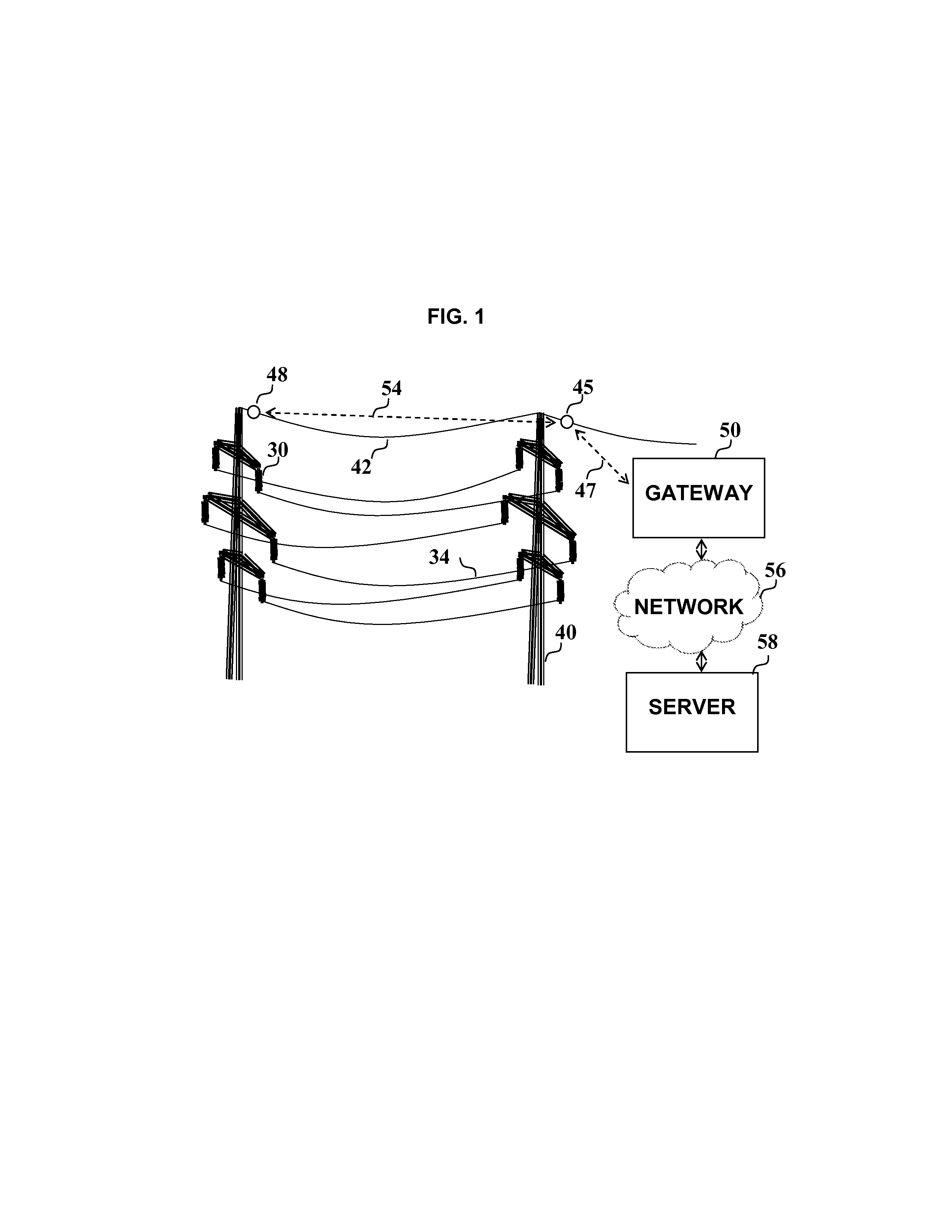
[0020]Reference is first made to FIG. 1, in which insulator strings such as insulator string 30, retain power wires such as power wire 34 in a suspended state. In some situations, a faulty or contaminated insulator string 30 is conducive to the development of partial discharges over the insulator strings. These partial discharges generate electromagnetic pulses, which are induced into the power wires such as power wire 34, tower 40 and ground wire 42.

[0021]According to a embodiment of the present invention, a sensor unit 45 is deployed on the ground wire 42, typically every one to three kilometers, which is capable of measuring the current pulses in the ground wire originating in the insulator string 30. The ratio between the magnitude of the partial discharge over the contaminated insulator string 30 and t...


PUM


Abstract

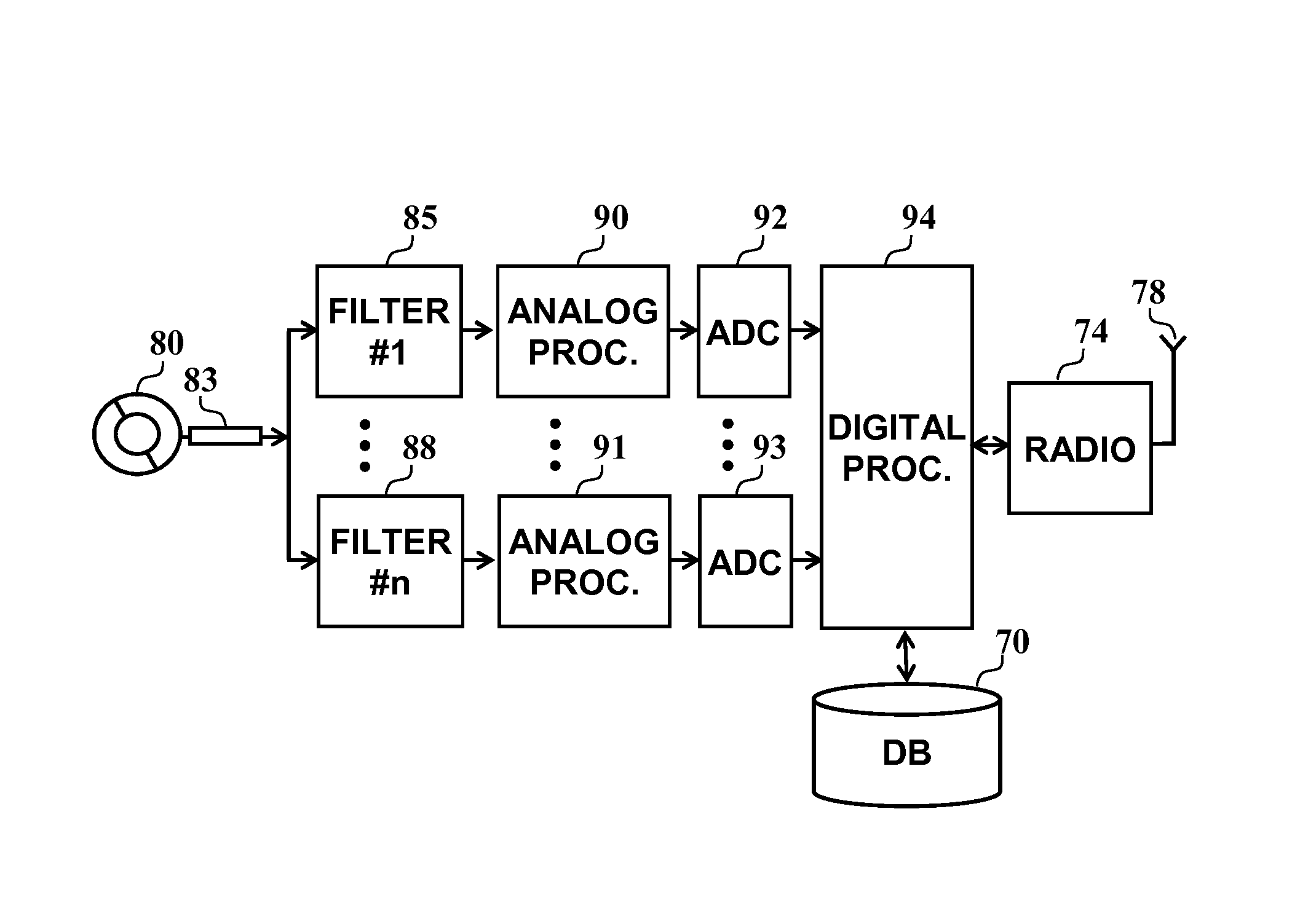
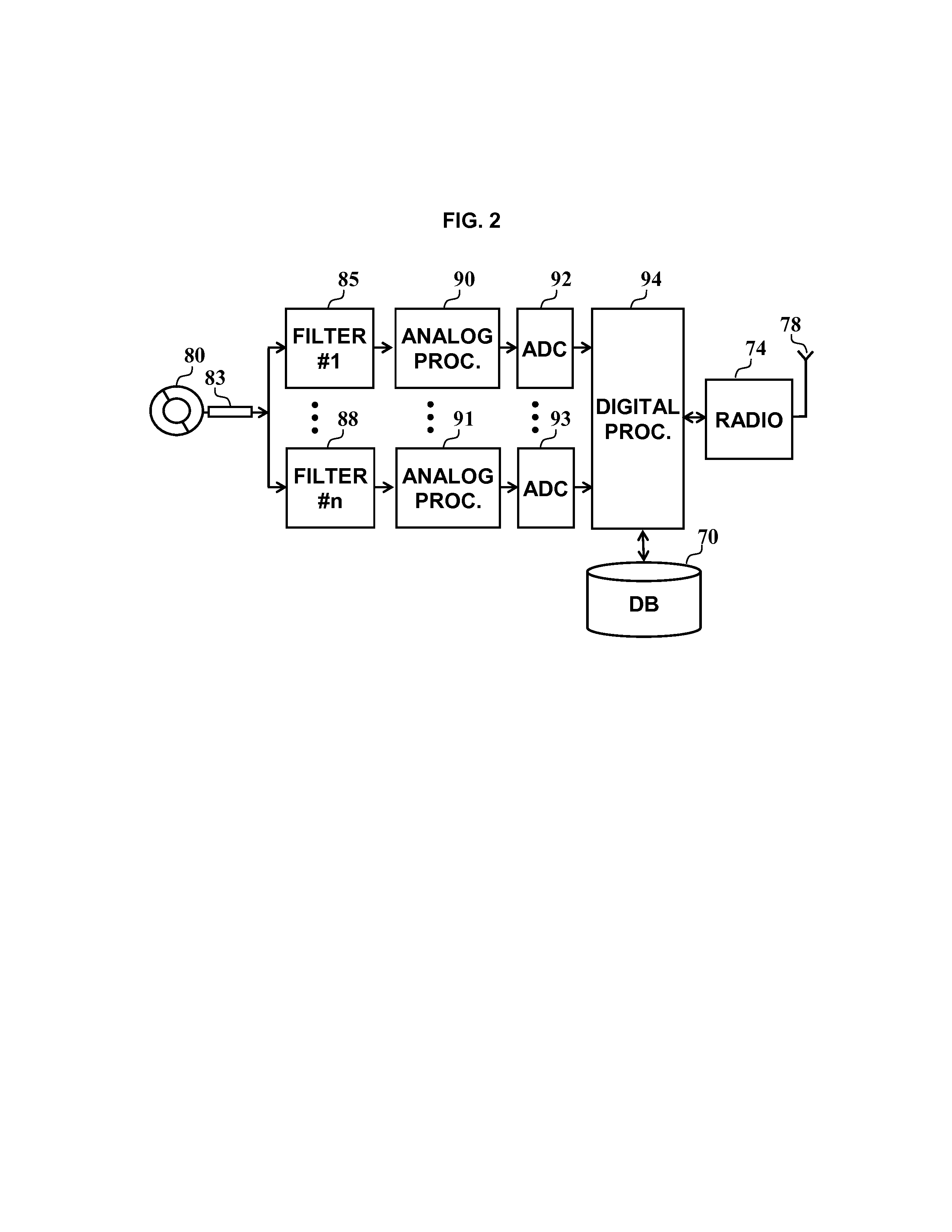
A system for the detection of discharges over high voltage power-line insulator strings of an electrical grid. A sensor unit is deployed on a non conducting cable of the grid. The sensor feeds an array of band cut-off filters receiving each signals from said at least one sensor unit. An analogue processor is associated with each of the band cut-off filters associated each with a current peak detector. An ADC unit is associated with each one of said analogue processors. In addition a digital processor is provided for calculating data received from each one of the ADCs and one radio transmitter unit sends data to a gateway of a network. A digital processor is adapted to send data processed based on the output of the ADCs, to the radio transmitter for conveying the data to processor associated with a WAN.

Description

CROSS-REFERENCE TO RELATED PATENT APPLICATIONS[0001]This application claims priority from U.S. provisional patent application 61 / 584,259 entitled “System and method for prediction of flashovers over high voltage power-line insulator strings”, filed on Jan. 8, 2012.FIELD OF THE INVENTION[0002]The present invention relates to monitoring transmission power lines of an electrical grid, and specifically, to quantifying occurrences of flashovers over contaminated power line isolators.BACKGROUND OF THE INVENTION[0003]Contamination over power line insulator-strings is a major source of power quality impairment. Such contamination can cause flashovers, which result in shortcuts and wide-area power sags (instantaneous voltage level drop). This causes significant damage to industrial power consumers. Electrical companies invest significant resources on washing insulator strings using helicopters and from the ground. Currently, the maintenance crews cannot get a view of the contamination level ...

Claims


Application Information

Patent Timeline
Patent Type & Authority Applications(United States)
IPC IPC(8): G01R31/08G01R31/02
CPCG01R31/1245G01R31/024G01R31/088
Inventor KNIJNIK, ROMANKOTTICK, DANIELMASLOVSKI, LEONIDWOLFSON, EDUARDFRENKEL, LIRON
Owner MEGGER GRID ANALYTICS LTD
Learn More