Supercharge Your Innovation With Domain-Expert AI Agents!

Method of actuating a wireless sensor of road construction equipment

a wireless sensor and road construction technology, applied in the direction of wireless architecture, instruments, roads, etc., can solve the problems of inability to achieve the same functionality of wireless sensors, affecting the operation of road construction equipment, and affecting the operation of road construction

Active Publication Date: 2013-07-18
DANFOSS POWER SOLUTIONS INC
View PDF2 Cites 2 Cited by
  • Summary
  • Abstract
  • Description
  • Claims
  • Application Information

AI Technical Summary

Benefits of technology

The patent is related to a way to turn on a wireless sensor on a road construction machine using a magnet. The sensor is attached to a bracket on the machine, and as the bracket is brought close to the magnet, the sensor is activated. This means that the sensor can be easily attached and detached from the machine for use in construction projects. The technical effect of this is that it allows for easier and more convenient use of wireless sensors in road construction equipment.

Problems solved by technology

Problems exist with utilizing such sensors because the cables are often subject to wear and potential damage by vehicle workers and the like.
While providing a system that utilizes wireless sensors improves upon the art problems still remain.
Specifically, old wired sensors could be disconnected from the machine battery power when the sensors were disconnected at night or when the machine was shut down for the night terminating the machine battery connection; however, wireless sensors do not present the same functionality.
Because of the road construction setting simply placing a mechanical switch on the sensor is not a viable option.
Specifically, as with the cable at road construction worksites, external mechanical switches would be bumped, hit, damaged and the like causing random power outages, adding cost for damaged equipment, and lost time in needed repairs.
In addition, utilizing a microprocessor in a low current sleep mode that would be actuated by an electronically activated switch also is not desirable because the sleep mode continuously drain power from the battery minimizing the amount of time and effectiveness of the wireless sensor.

Method used


Image

  • Method of actuating a wireless sensor of road construction equipment
  • Method of actuating a wireless sensor of road construction equipment
  • Method of actuating a wireless sensor of road construction equipment

Examples


Embodiment Construction

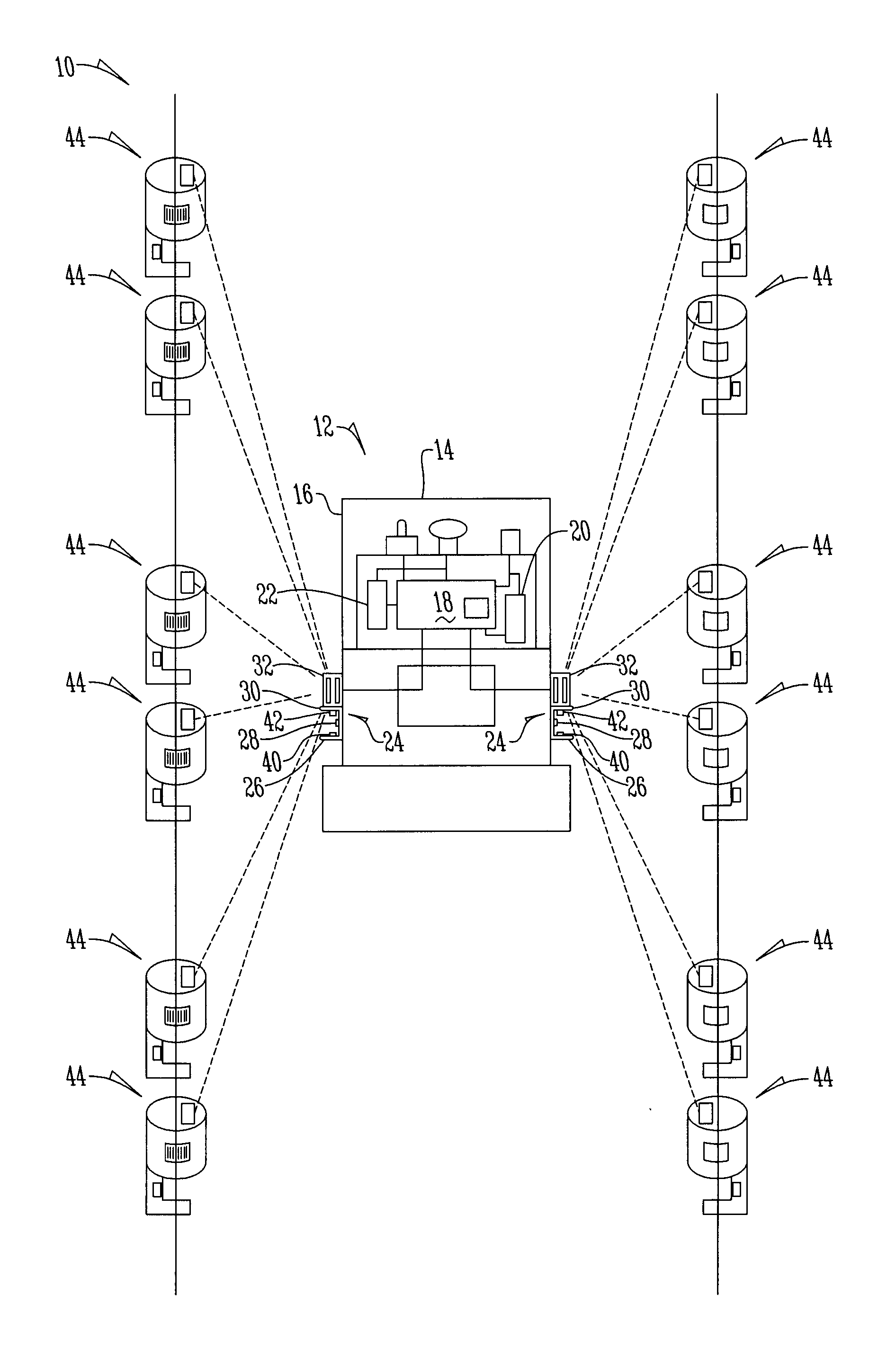
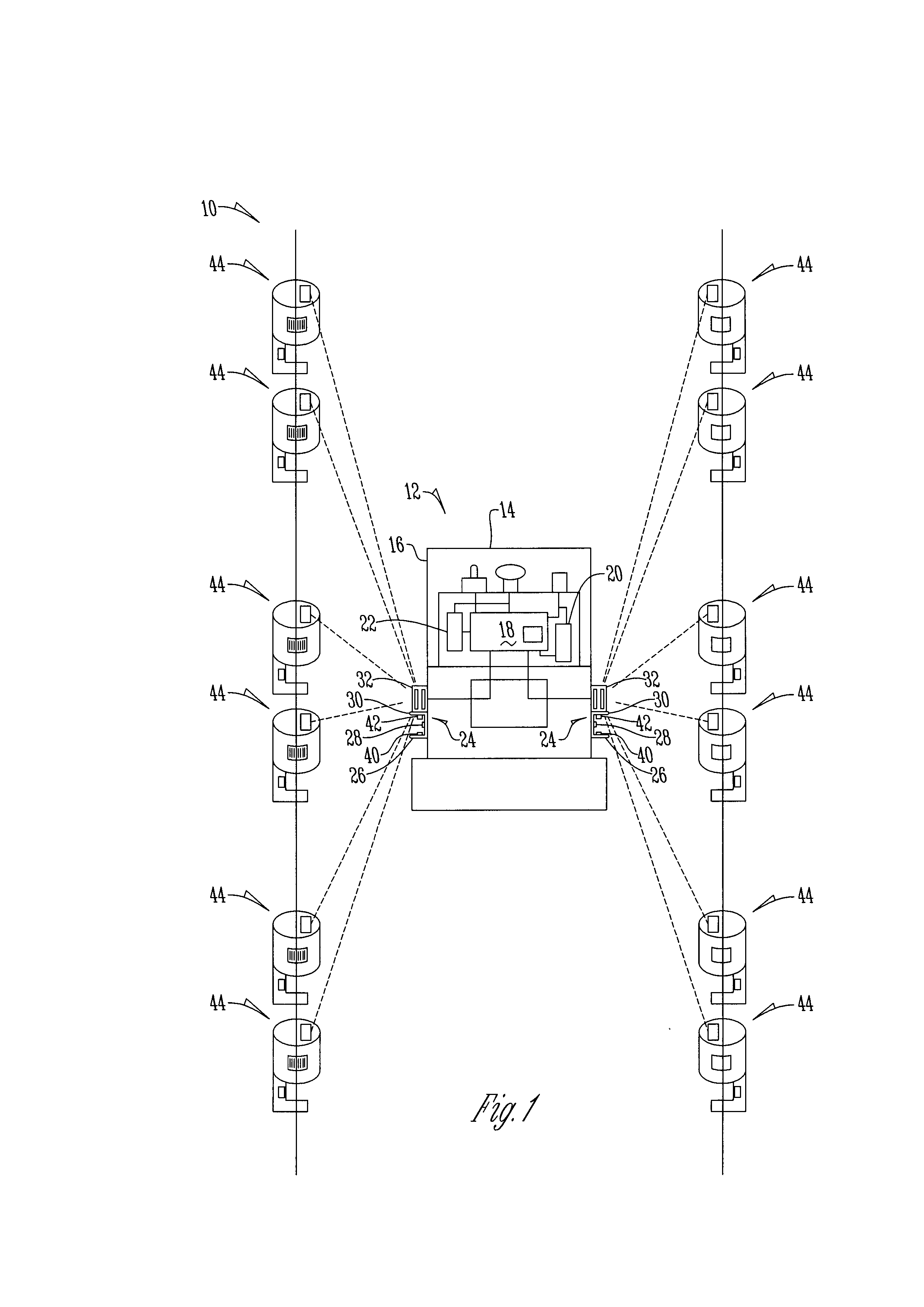
[0013]FIG. 1 shows a sensor system 10 for road construction equipment 12 that includes a road construction machine 14. In one embodiment the road construction machine is a vehicle such as a paver that has a frame 16 that houses a master control 18 that operates valving 20 and a steering device 22 in order to control the steering and elevation of the vehicle 14.

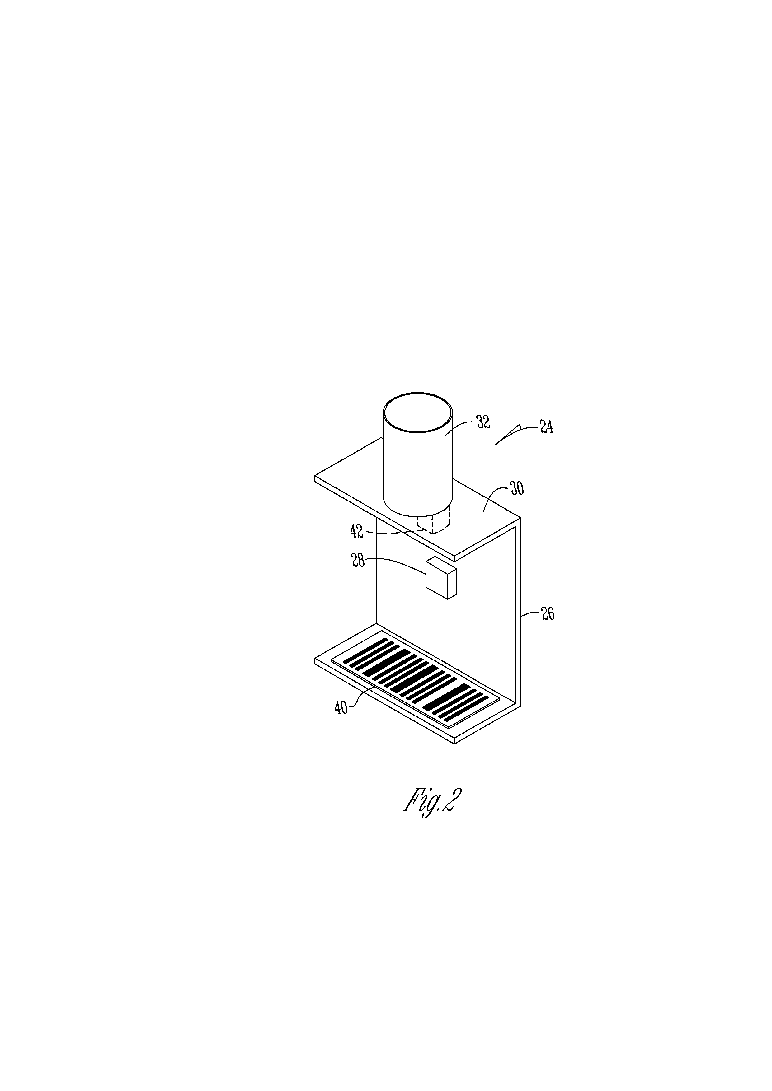
[0014]A bracket assembly 24 is secured to the road construction machine 14 by bolting or securing the bracket to the machine 14 in order to affix the bracket assembly 24 to the frame 16. The bracket assembly includes a bracket 26, a magnet 28 detachably secured to the bracket, an attachment section 30 that is in spaced relation to the magnet and is of size and shape to receive and fixedly hold in place a wireless sensor 32.

[0015]The bracket assembly 24 also includes a machine readable medium 40 affixed adjacent in spaced relation to the mounting section 28. The machine readable medium 40 in a preferred embodiment is a radio fr...


PUM

PropertyMeasurementUnit
poweraaaaaaaaaa
elevationaaaaaaaaaa
sizeaaaaaaaaaa

Abstract

A method of actuating a wireless sensor of road construction equipment. A bracket is secured to the road construction equipment that has a magnet and is able to receive a wireless sensor. An actuator is disposed within the housing of the wireless sensor that reacts to the magnetic field created by the magnet such that when the wireless sensor is attached to the bracket the sensor is operable and when detached from the bracket no longer operates.

Description

BACKGROUND OF THE INVENTION[0001]This invention relates to a method of actuating a wireless sensor. More specifically, this invention relates to a method of actuating a wireless sensor of road construction equipment that minimizes battery use.[0002]In the road construction arts sensors are utilized in association with vehicles such as road pavers and the like to assist in the operation of the vehicles. For example, currently sensors are mounted on a vehicle and have a cable that connects the sensor to secondary sensors presented on a string line such that a master controller of the vehicle that is in communication with the sensor operates the steering and leveling of the vehicle to ensure that the vehicle is moving in a straight line.[0003]Problems exist with utilizing such sensors because the cables are often subject to wear and potential damage by vehicle workers and the like. Thus, a need exists in the art to eliminate cables. Recently, Applicant has presented solutions in the fo...

Claims


Application Information

Patent Timeline
Patent Type & Authority Applications(United States)
IPC IPC(8): H05K13/00
CPCE01C19/004G08C17/04H04Q9/00Y10T29/49004Y10T29/4902Y10T29/49002H04Q2209/47
Inventor ZENG, JACK
Owner DANFOSS POWER SOLUTIONS INC
Features
  • R&D
  • Intellectual Property
  • Life Sciences
  • Materials
  • Tech Scout
  • Unparalleled Data Quality
  • Higher Quality Content
  • 60% Fewer Hallucinations
Learn More