Waste heat boiler

Inactive Publication Date: 2013-07-18
HALDOR TOPSOE AS
View PDF8 Cites 6 Cited by
  • Summary
  • Abstract
  • Description
  • Claims
  • Application Information

AI Technical Summary

Benefits of technology

[0010]An object of this invention is to avoid the drawbacks of the known waste heat boilers by providing

Problems solved by technology

The mechanical design and, in particular, dimensioning of the heat exchanging surface in shell-and-tube exchanger type boilers represent certain problems.
Fire-tube boiler applications involve high pressures on the shell side or on both sides, and considerable temperature differences between the shell side and the tube side.
After a certain time, on stream fou

Method used


Image

  • Waste heat boiler
  • Waste heat boiler
  • Waste heat boiler

Examples


Example

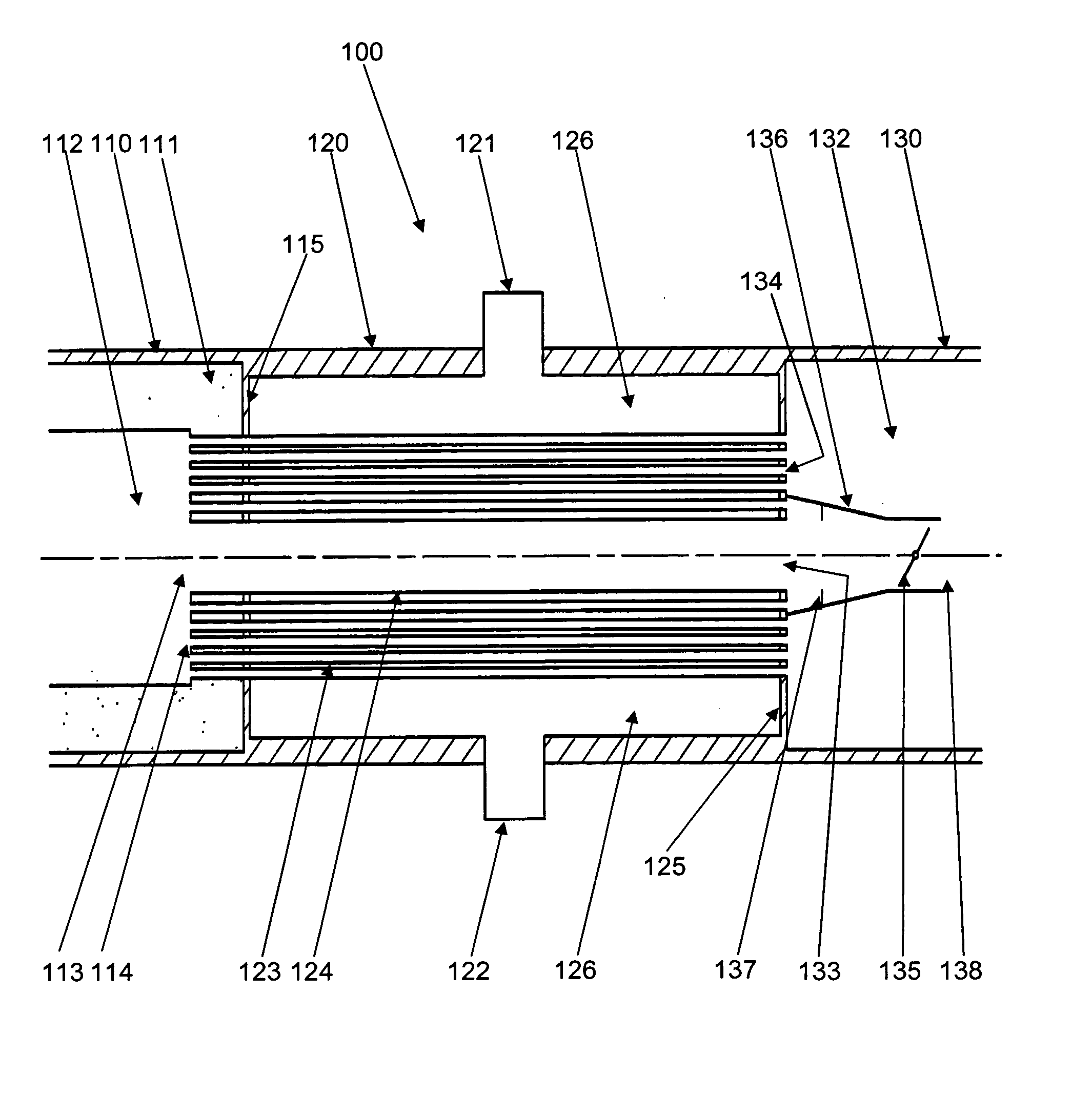
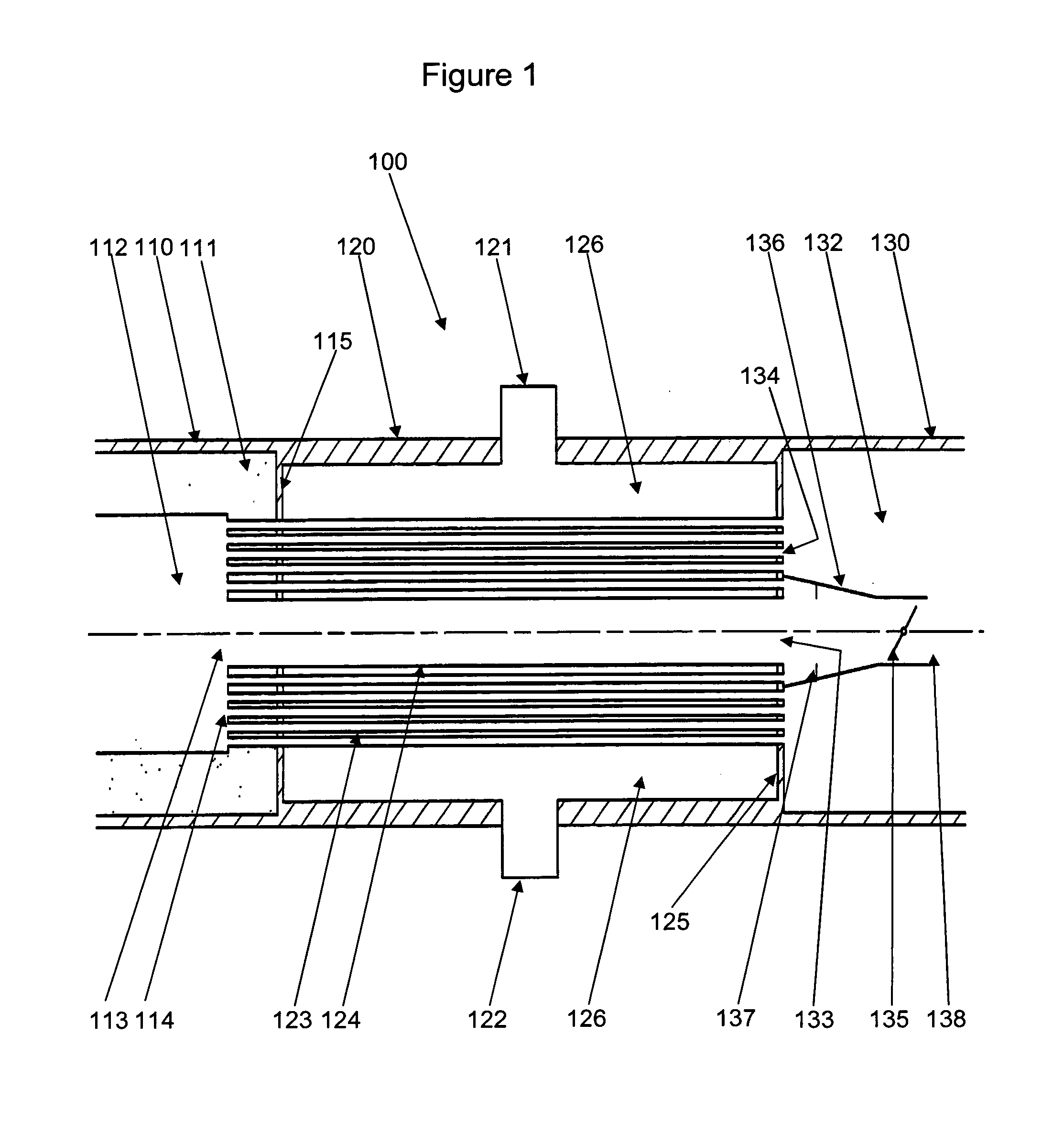
[0061]FIG. 1 is a cross sectional view of the waste heat boiler 100 according to an embodiment of the invention. The waste heat boiler comprises a first shell part, process gas inlet end 110; a second shell part, heat exchange section 120 and a third shell part, process gas outlet end 130; all having a substantially cylindrical shape and substantially the same diameter, but as can be seen on the figure, not necessarily the same material thickness. The material thickness as well as the choice of material can be varied depending on the process conditions.

[0062]A first tube sheet, process gas inlet end 115 separates the first shell part from the second shell part. Likewise, a second tube sheet, process gas outlet end 125 separates the second shell part from the third shell part. Thus the first shell part and the first tube sheet encloses the process gas inlet section 112; the second shell part along with the first and the second tube sheet encloses the heat exchange section 126; and th...


PUM


Abstract

A waste heat boiler has heat exchange tubes for indirect heat exchange of a relatively hot process gas and a cooling media, and a by-pass tube for by-passing a part of the process gas; a process gas collector collects and mixes a part of the heat exchanged process gas and at least a part of the by-passed process gas before the mix is lead via a control valve to the process gas outlet of the waste heat boiler together with the rest of the heat exchanged process gas.

Description

BACKGROUND OF THE INVENTION[0001]The present invention is directed to the recovery of waste heat from chemical reactions. More particularly, the invention relates to a waste heat boiler with improved control of cooling effect.[0002]Waste heat boilers are most generally used for the generation of steam by waste heat recovered from hot process streams. Typically, those boilers are designed as shell-and-tube exchangers with a plurality of heat exchanging tubes arranged within a cylindrical shell.[0003]Two basic types of shell-and-tube exchangers are employed in the industry, the water-tube type, in which water / steam mixtures flow through the tubes, and the fire-tube type having the heating process stream inside the tubes.[0004]The characteristic components of the boiler are the tubes mounted in tubesheets at a front-end head and a rear-end head within the shell. In the fire-tube boilers steam production is accomplished on the shell side of the tubes by indirect heat exchange of a hot p...

Claims


Application Information

Patent Timeline
IPC IPC(8): F22B35/00F28F27/02F28D7/10F22B1/18
CPCF22B1/18F22B1/1838F22B9/12F22B35/001F28D7/163F28F2265/00F28F27/02F28F2250/06F22B35/007F28D7/103F28D21/001
Inventor CHRISTIANSEN, HANS GEORG
Owner HALDOR TOPSOE AS
Why Eureka
Try Eureka