Valve for Use in Chemical Injectors and the Like

Inactive Publication Date: 2013-07-18
BAKER HUGHES INC
View PDF6 Cites 11 Cited by
  • Summary
  • Abstract
  • Description
  • Claims
  • Application Information

AI Technical Summary

Benefits of technology

The invention is about improving check valve designs that reduce fluid cavitation, which means the valve reduces the formation of bubbles. The valve also reduces damage to the valve seat caused by erosion, which means the valve is less likely to get damaged.

Problems solved by technology

Cavitation of fluid passing through the check valve can cause undesirable erosion of the check valve ball and seat.

Method used


Image

  • Valve for Use in Chemical Injectors and the Like
  • Valve for Use in Chemical Injectors and the Like
  • Valve for Use in Chemical Injectors and the Like

Examples


Embodiment Construction

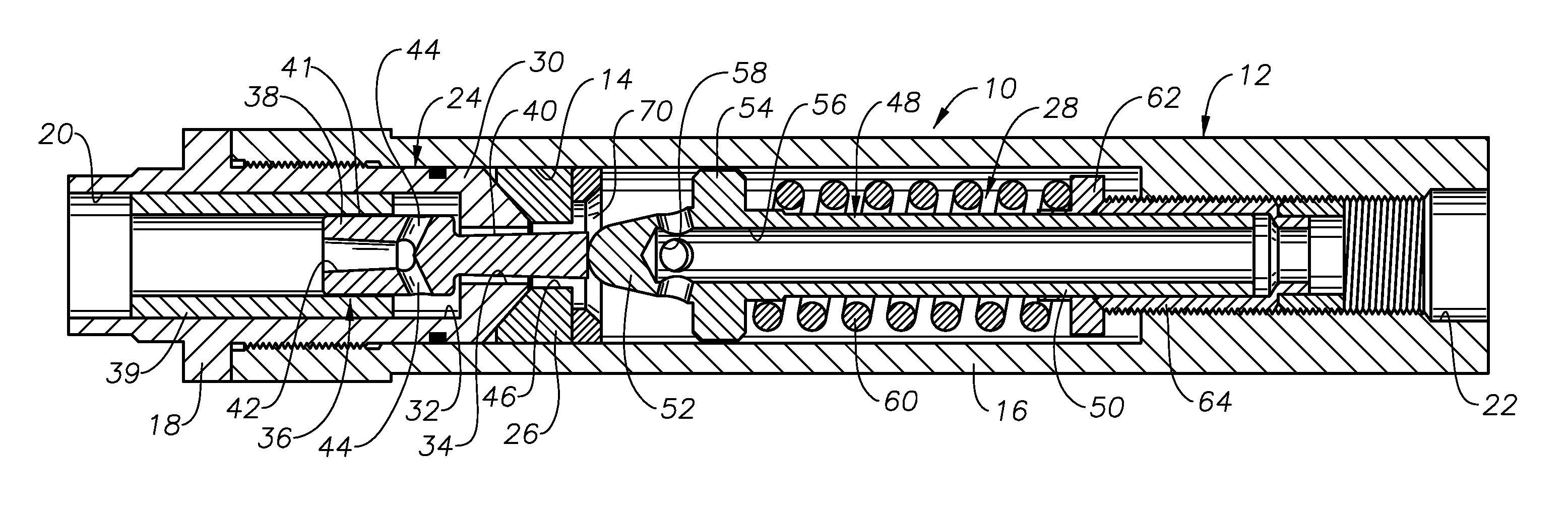
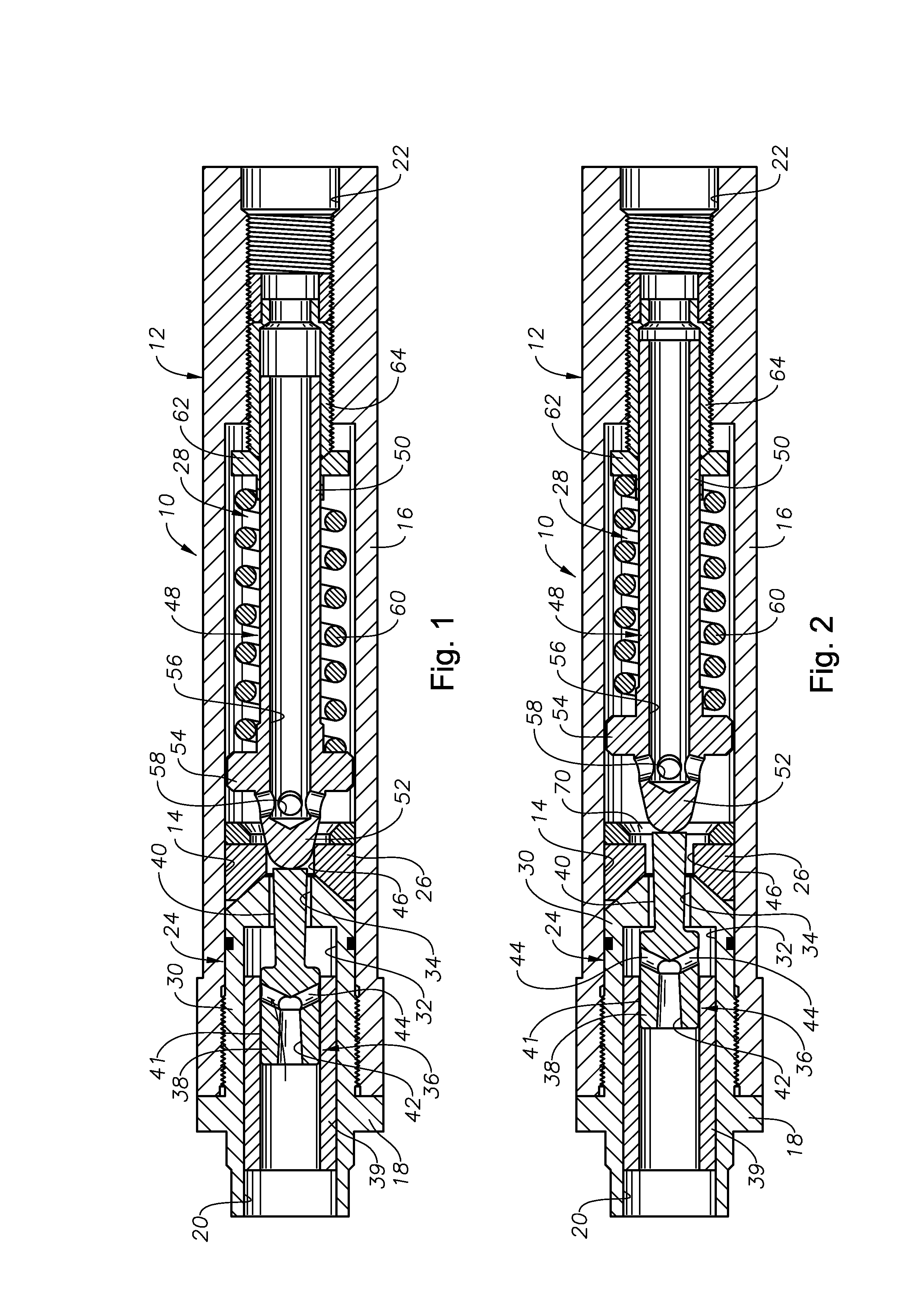
[0013]FIGS. 1-2 illustrate an exemplary valve 10 which has been constructed in accordance with the present invention. The valve 10 includes an outer housing 12 that defines an inner axial bore 14 along its length. In the depicted embodiment, the housing 12 is made up of a primary housing member 16 and an affixed cap 18. Axial ends of the housing 12 provide a fluid inlet 20 and a fluid outlet 22. The housing 12 may be provided with suitable threaded end portions (not shown) for incorporation of the valve into a flow line or other fluid flow path.

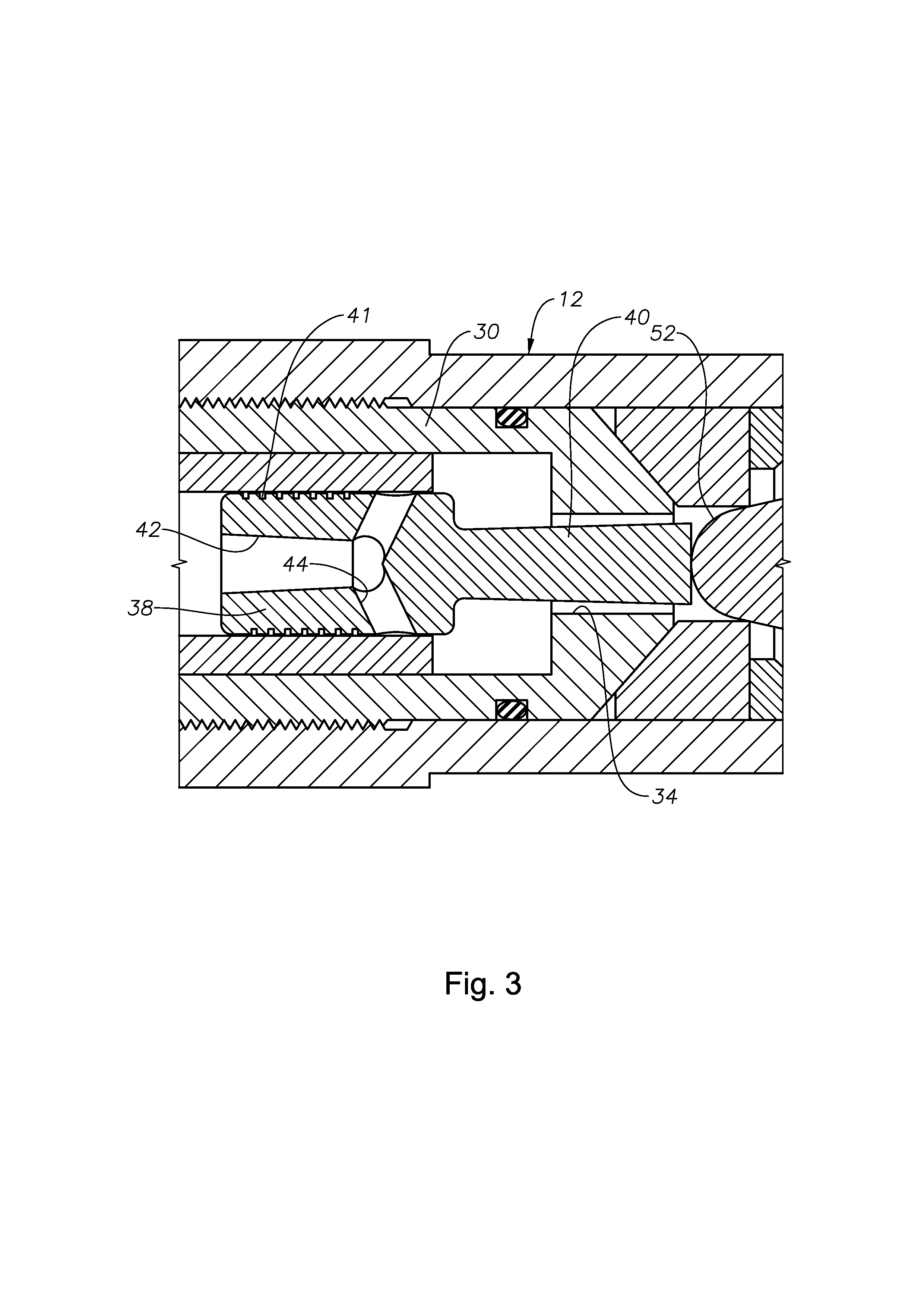
[0014]The axial bore 14 generally contains a piston assembly 24, a valve seat 26, and a check dart assembly 28. The piston assembly 24 includes a piston housing 30 that defines an enlarged-diameter inner chamber 32 and a reduced-diameter inner chamber 34. The piston housing 30 is fixedly secured within the bore 14. Piston member 36 is moveably disposed within the inner chambers 32, 34. The piston member 36 includes an enlarged base portion 38...


PUM


Abstract

A valve having an outer housing defining a central bore with a fluid inlet and a fluid outlet. A check dart assembly, valve seat and piston assembly are retained within the central bore. The valve is moveable between open and closed positions in response to fluid flow into the fluid inlet of the valve.

Description

[0001]The present application claims priority to U.S. provisional patent application Ser. No. 61 / 533,323 filed Sep. 12, 2011.BACKGROUND OF THE INVENTION[0002]1. Field of the Invention[0003]The present invention generally relates to check valves.[0004]2. Description of the Related Art[0005]A common form of check valve is a ball member that is biased against a valve seat by a spring. Check valves are used to provide one way flow in a wide variety of applications, including chemical injection devices. Cavitation of fluid passing through the check valve can cause undesirable erosion of the check valve ball and seat.SUMMARY OF THE INVENTION[0006]The present invention provides improved check valve designs that reduce fluid cavitation. In addition, the design of the valve reduces erosion around the valve seat.BRIEF DESCRIPTION OF THE DRAWINGS[0007]The advantages and other aspects of the invention will be readily appreciated by those of skill in the art and better understood with further re...

Claims


Application Information

Patent Timeline
IPC IPC(8): F16K17/04F16K17/06F16K15/02
CPCF16K15/063F16K15/025E21B41/02F16K17/06E21B37/06F16K17/046Y10T137/7929Y10T137/0318Y10T137/7845
Inventor HE, ZHI YONGHOLT, JAMESREES, ROBERTWHITLEY, GERALDMEIER, KYLE
Owner BAKER HUGHES INC
Why Eureka
Try Eureka