Device to generate lift force (options)

Inactive Publication Date: 2013-07-18
AKHMEJANOV ALIBI
View PDF4 Cites 15 Cited by
  • Summary
  • Abstract
  • Description
  • Claims
  • Application Information

AI Technical Summary

Benefits of technology

[0007]The aim of invention is achieving of technical result: reduction of energy losses on the creating and change of vector of moving, aerodynamic, composite force, including as a

Problems solved by technology

Textbook for high technical schools—3-rd edition, revised and corrected—M., Vysshaya Shkola, 1980.—416 pages), meanwhile the above mentioned device is characterized with ineffective control of change of vector of moving, aerodynamic, composite force, including as a component a lift force, ineffective control of space motion, what is caused by restriction of degree of freedom of travel of such units as a fixed annular wing, steering flappers.
Common disadvantages of specified analogues are high energy losses while creating and change of vector of moving, aer

Method used


Image

  • Device to generate lift force (options)
  • Device to generate lift force (options)
  • Device to generate lift force (options)

Examples


Example

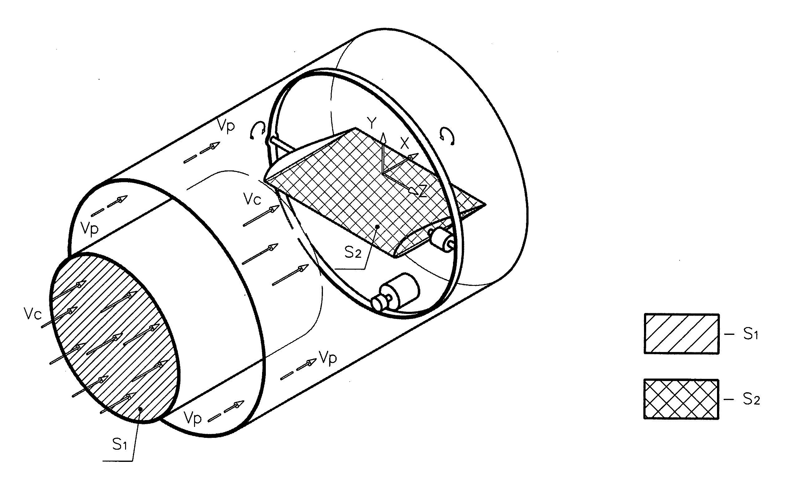
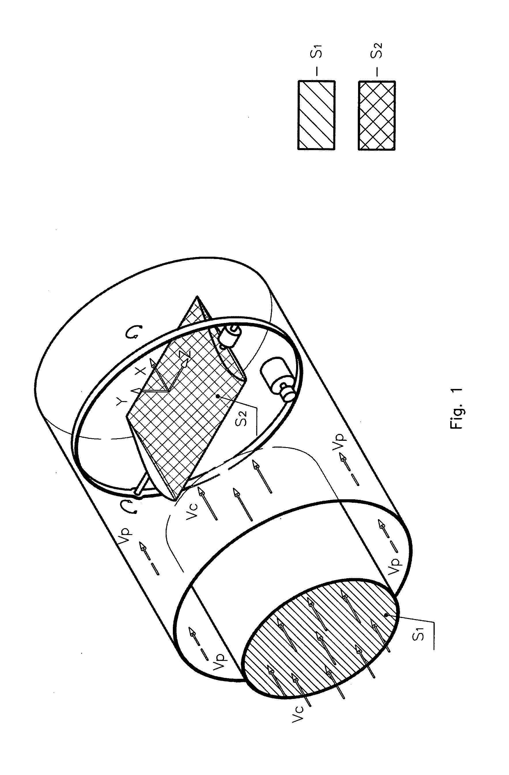
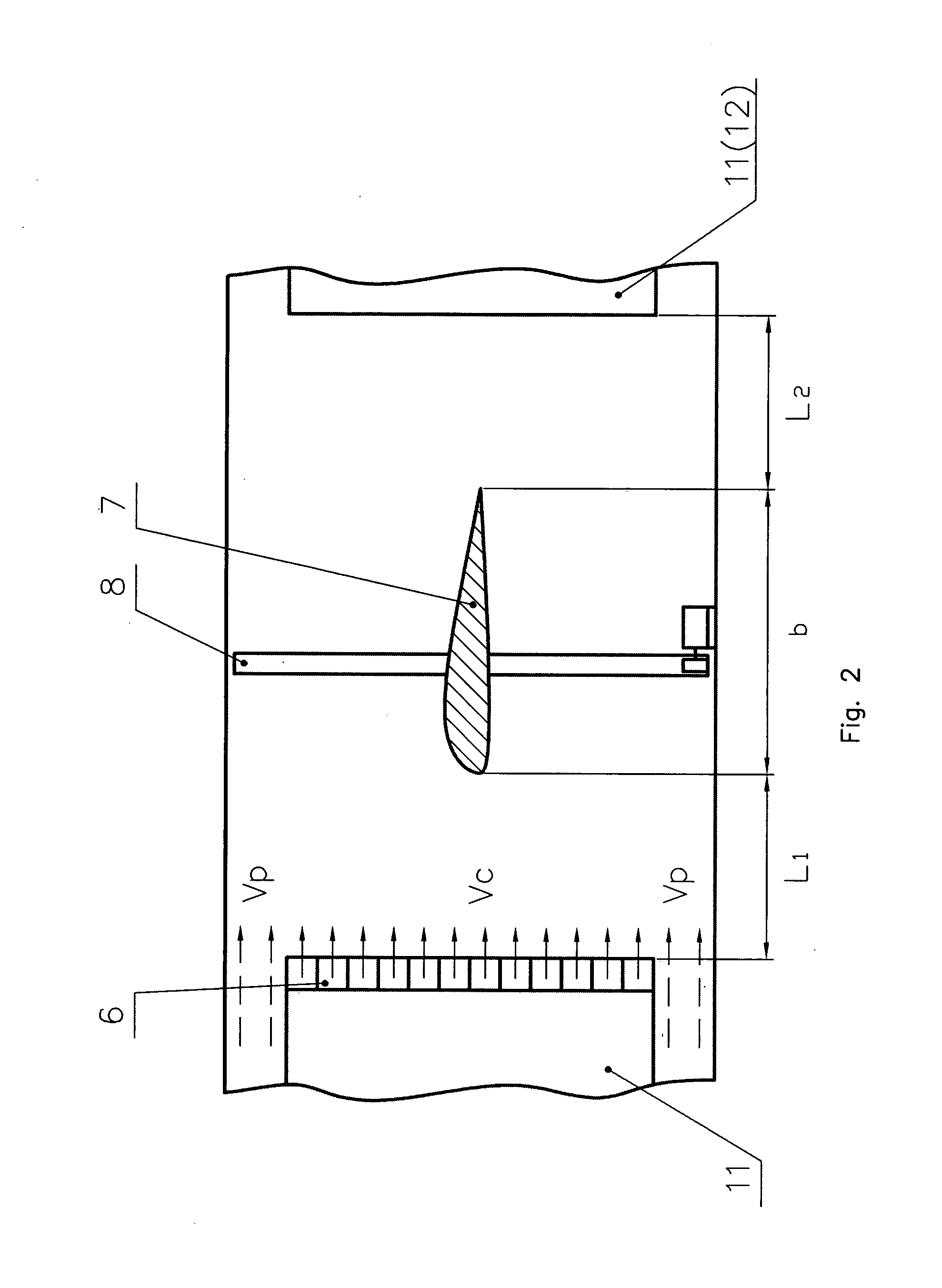
[0018]All three options of a device contain a frame 1, main superchargers 2, peripheral superchargers 3, driving motor 4, drive shaft (power transmission) 5, guiding devices 6, wings 7, are equipped with adjusting units 8 (including special driving motors), unit to connect outdoor environment 9 (for heat and mass exchange), the system to maintain the required working temperature of medium 10, separating tubiform elements 11, additional separating tubiform elements 12.

[0019]In case of a device as per the second option it additionally has a central distributive unit to change the path of peripheral and central flow 13.

[0020]In case of a device as per the third option, it additionally equipped with end elements 14, having inside profiled surfaces in order to provide the turn back of working medium flow at 180°, profiled in such a manner, that it gives the possibility to decrease the creation of nonstationary aerodynamic processes due to flow turbulence and accordingly decrease energy l...


PUM


Abstract

The options of the invention relate to the aviation and can be used in order to create lifting vehicle as well as load lifting devices. In order to achieve technical result—the decrease of energy losses on the while creating and change of vector of moving, aerodynamic, composite force, including as a component a lift force,—in the device to generate lift force containing a tubiform frame, superchargers, the wings having in section an aerofoil profile oriented by the leading edge to the direction of working medium exhaust out of the super-charger, adjusting units for a wing, guiding devices, each of those is installed in front of leading edge of each wing, the system to maintain the required working temperature of medium, unit to connect outdoor environment, as per the invention in the first option of the device a tubiform frame is of the form of a tore, in the second option—the form of closed volumetric loop, in the third option—a cylindrical form. Meanwhile each option of the device is equipped with relevant distinguishing units, providing the achieving of a technical result.

Description

TECHNICAL FIELD[0001]The invention relates to the aviation and can be used in order to create lifting vehicle as well as load lifting devices.BACKGROUND ART[0002]It is known the device to generate lift force in the form of lifting vehicle, in which between the bottoms and the tops of round frame, which contain center superchargers in the shape of horizontally located ventilators, in the zone of annular plenum the annular wing in the form of upturned plate with a shape flat-convex in section is fixed, a lifting vehicle in order to intake air contains bottom and top air inlet ducts (a unit to connect outdoor environment), steering flappers and power device (driving motor) for a supercharger (Patent RU N22061627 , IPC C1 5B64 C29 / 00 dated 10 Jun. 1996). Lift force is derived due to the unsymmetrical flow-around of a wing (Physics encyclopedia / Head Editor A. M. Prokhorov.—Moscow: Soviet encyclopedia, 1983.-928 pages; Krasnov N. F. Aerodynamics. Part I. Theoretic framework. Aerodynamics ...

Claims


Application Information

Patent Timeline
IPC IPC(8): B64C39/06
CPCB64C39/062B64C39/00B64C39/001
Inventor AKHMEJANOV, ALIBI
Owner AKHMEJANOV ALIBI
Why Eureka
Try Eureka