
Auto-focus image system

a technology of image system and autofocus, which is applied in the field of autofocus electronically captured images, can solve the problems of small detection point group, ineffective technique, and inconvenient contrast technique for motion video

Inactive Publication Date: 2013-07-18
TAY HIOK NAM
View PDF10 Cites 11 Cited by
  • Summary
  • Abstract
  • Description
  • Claims
  • Application Information

AI Technical Summary

Benefits of technology

The patent text describes a method for reducing edge contributions to a focus signal by measuring the shape of the edge. The method uses a generator to assign a lower weight to the edge based on the shape measures of the gradient profile. This weight is reduced if the shape measures fall outside a certain region. The method also assigns a higher weight to a shape that has perfect reflection symmetry. The technical effect of this method is to improve the accuracy and reliability of focus signals by reducing edge contributions.

Problems solved by technology

Although acceptable for still pictures the contrast technique is not suitable for motion video.
Having a small group of detection points is prone to error because noise may be superimposed onto one or more points.
This technique is also ineffective if the detection points do not coincide with an image edge.
This can be problematic in dim settings where the image light intensity is already low.

Method used


Image

  • Auto-focus image system
  • Auto-focus image system
  • Auto-focus image system

Examples


Embodiment Construction

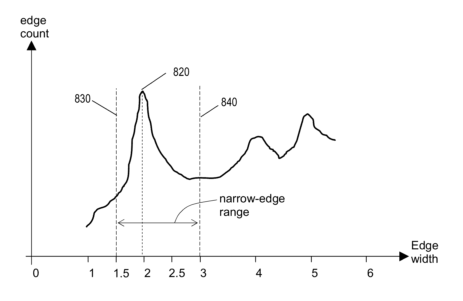
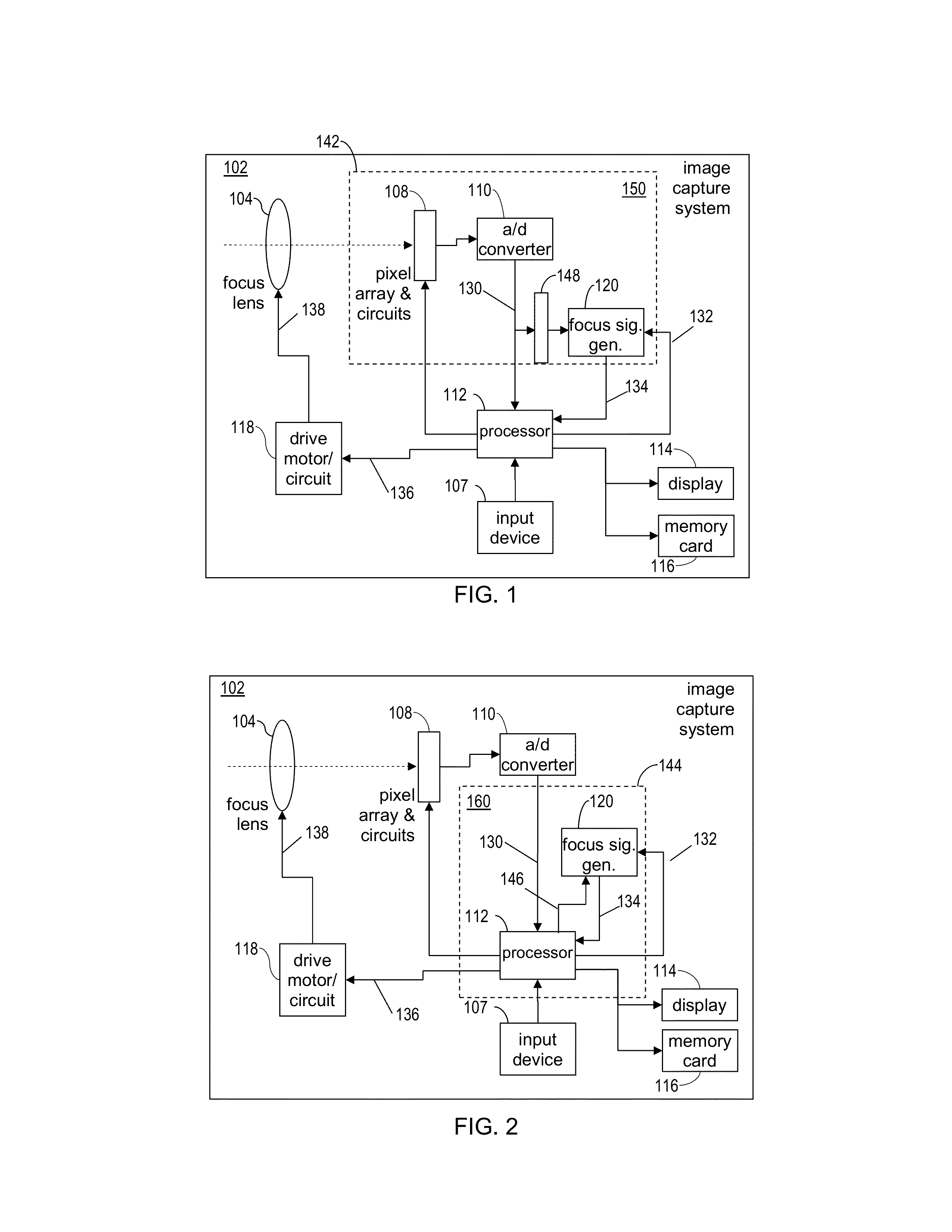
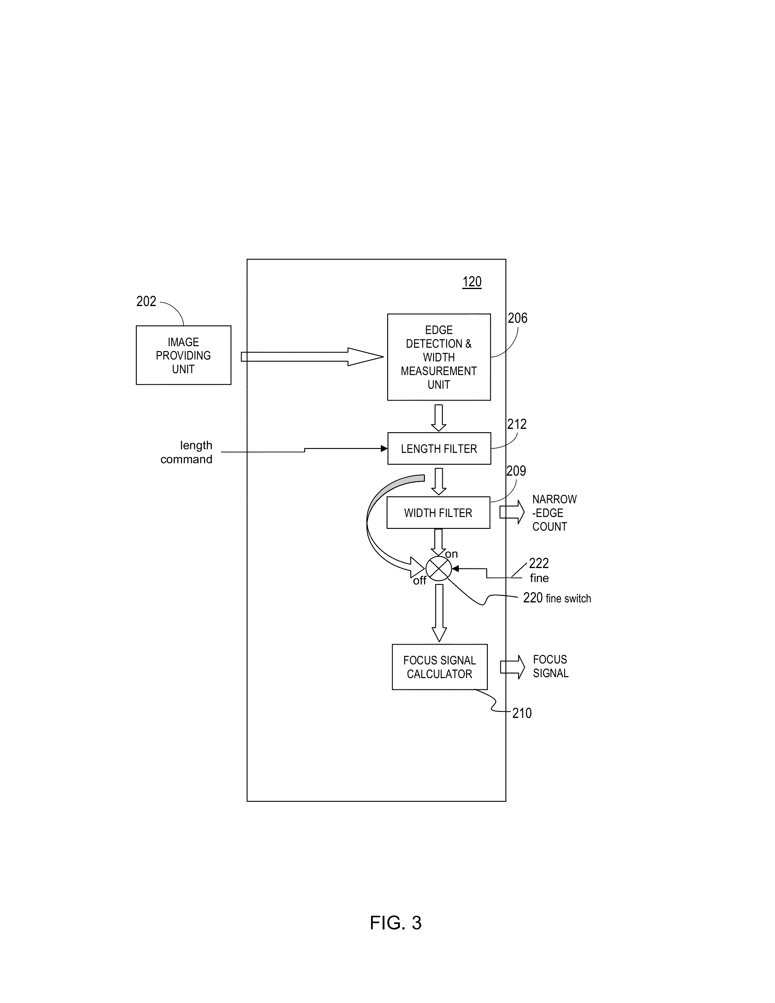
[0148]Disclosed is an auto focus image system that includes a pixel array coupled to a focus signal generator. The pixel array captures an image that has at least one edge with a width. The focus signal generator may generate a focus signal that is a function of the edge width and / or statistics of edge widths. An auto focus image system that includes a pixel array coupled to a focus signal generator. The pixel array captures an image that has at least one edge with a width. The generator generates a focus signal that is a function of the edge width and various statistics of edge width. The generator may eliminate an edge having an asymmetry of a gradient of an image signal. The generator may also eliminate an edge that fails a template for an associated peaking in the gradient. A processor receives the focus signal and / or the statistics of edge widths and adjusts a focus position of a focus lens. The edge width can be determined by various techniques including the use of gradients. ...


PUM


Abstract

An auto-focus image system includes a focus signal generator and a pixel array coupled thereto that captures an image that includes a plurality of edges. The generator computes a focus signal from a plurality of edge-sharpness measures, each measured from and contributed by a different edge as a quantity with a unit that is a power of a unit of length. The generator reduces a relative weight of the contribution of an edge depending on a shape of a normalized gradient profile of the edge as identified by an n-tuple of values of n different shape measures (n≧2). Each shape measure varies across normalized gradient profiles of different shapes. One shape measure may be the edge-sharpness measure itself. The weight may be zero if the n-tuple falls outside a predetermined region. At least one symmetrical shape that has perfect reflection symmetry receives reduced weight.

Description

CROSS-REFERENCE TO RELATED APPLICATIONS[0001]This patent application claims priority under 35 U.S.C. §119(e) to U.S. Provisional Patent Application No. 61 / 587,105 filed on Jan. 16, 2012.BACKGROUND OF THE INVENTION[0002]1. Field of the Invention[0003]The subject matter disclosed generally relates to auto-focusing electronically captured images.[0004]2. Background Information[0005]Photographic equipment such as digital cameras and digital camcorders may contain electronic image sensors that capture light for processing into still or video images, respectively. Electronic image sensors typically contain millions of light capturing elements such as photodiodes.[0006]Many image capturing devices such as cameras include an auto-focusing system. The process of auto-focusing includes the steps of capturing an image, processing the image to determine whether it is in focus, and if not, generating a feedback signal that is used to vary a position of a focus lens (“focus position”). There are ...

Claims


Application Information

Patent Timeline
Patent Type & Authority Applications(United States)
IPC IPC(8): G06K9/48
CPCG02B7/36H04N5/23212G06T2207/30168G06T7/0002G06T7/0085G06T7/13H04N23/673
Inventor TAY, HIOK NAM
Owner TAY HIOK NAM
Learn More