Communication cable apparatus including switch turned off in reverse connection state of communication cable apparatus

Active Publication Date: 2013-07-18
PANASONIC INTELLECTUAL PROPERTY MANAGEMENT CO LTD
View PDF22 Cites 26 Cited by
  • Summary
  • Abstract
  • Description
  • Claims
  • Application Information

AI Technical Summary

Benefits of technology

[0035]Since the communication cable apparatus of the first aspect of the present disclosure includes the above-described switch and the above-described control circuit, the breakdown of the communication cable apparatus can be prevented in the reverse connection state.
[0036]In addition, each of the transmitter apparatus of the second aspect of the present disclosure, the receiver apparatus of the third aspect of the present di

Problems solved by technology

Therefore, if an HDMI optical active cable is reversely connected between the source device and the sink device, the video and audio signal from the source device is disadvantageously outputted to the optical receiver circuit of the HDMI optical active cable, and the HDMI optical active cable does not normally operate.
As a result, t

Method used


Image

  • Communication cable apparatus including switch turned off in reverse connection state of communication cable apparatus
  • Communication cable apparatus including switch turned off in reverse connection state of communication cable apparatus
  • Communication cable apparatus including switch turned off in reverse connection state of communication cable apparatus

Examples


first embodiment

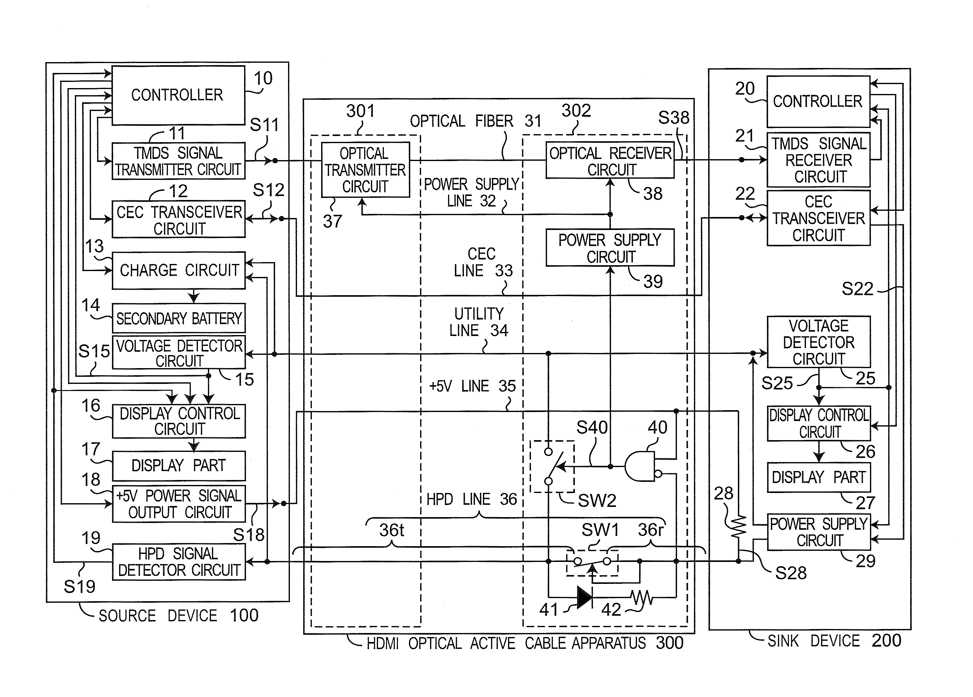
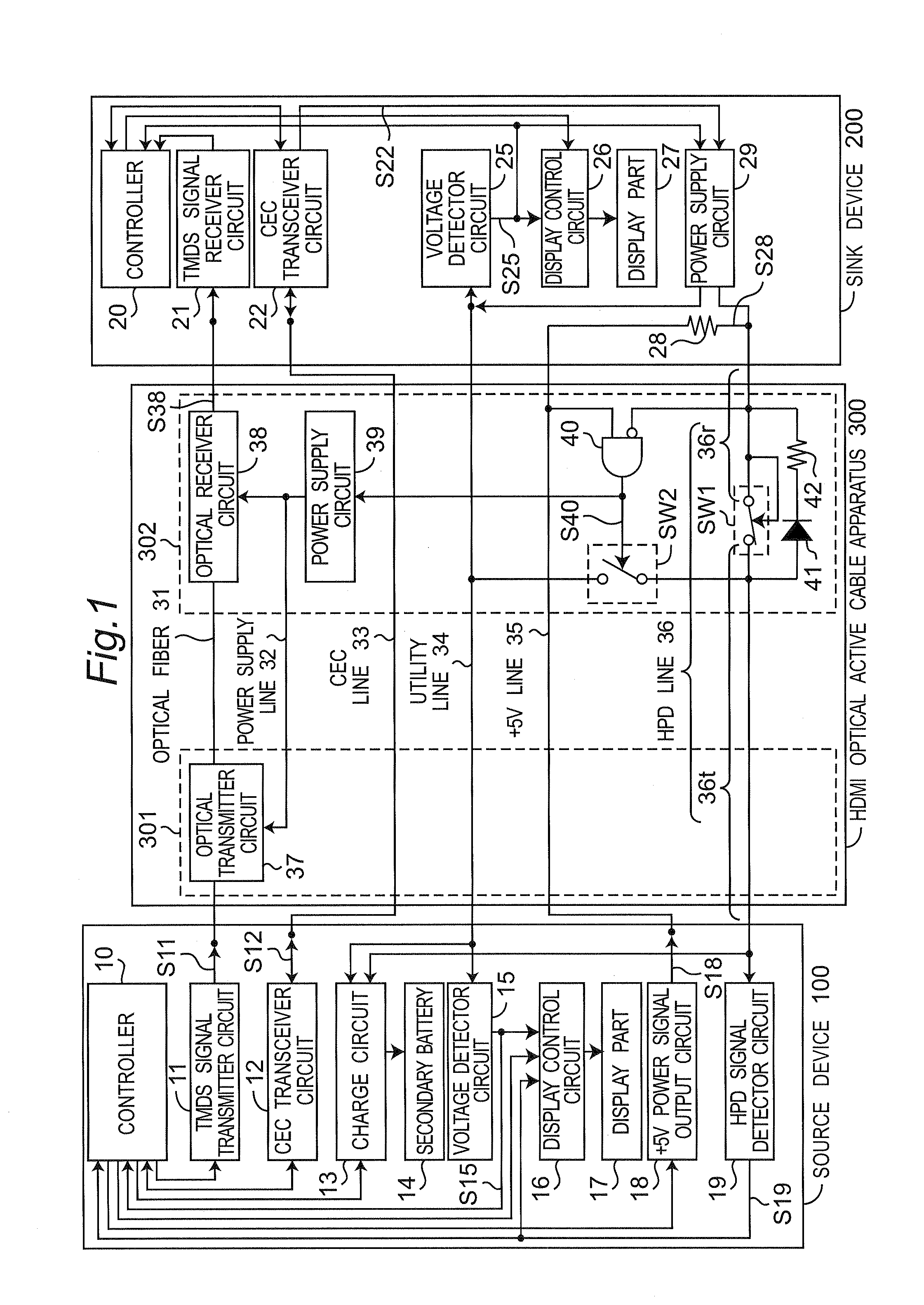
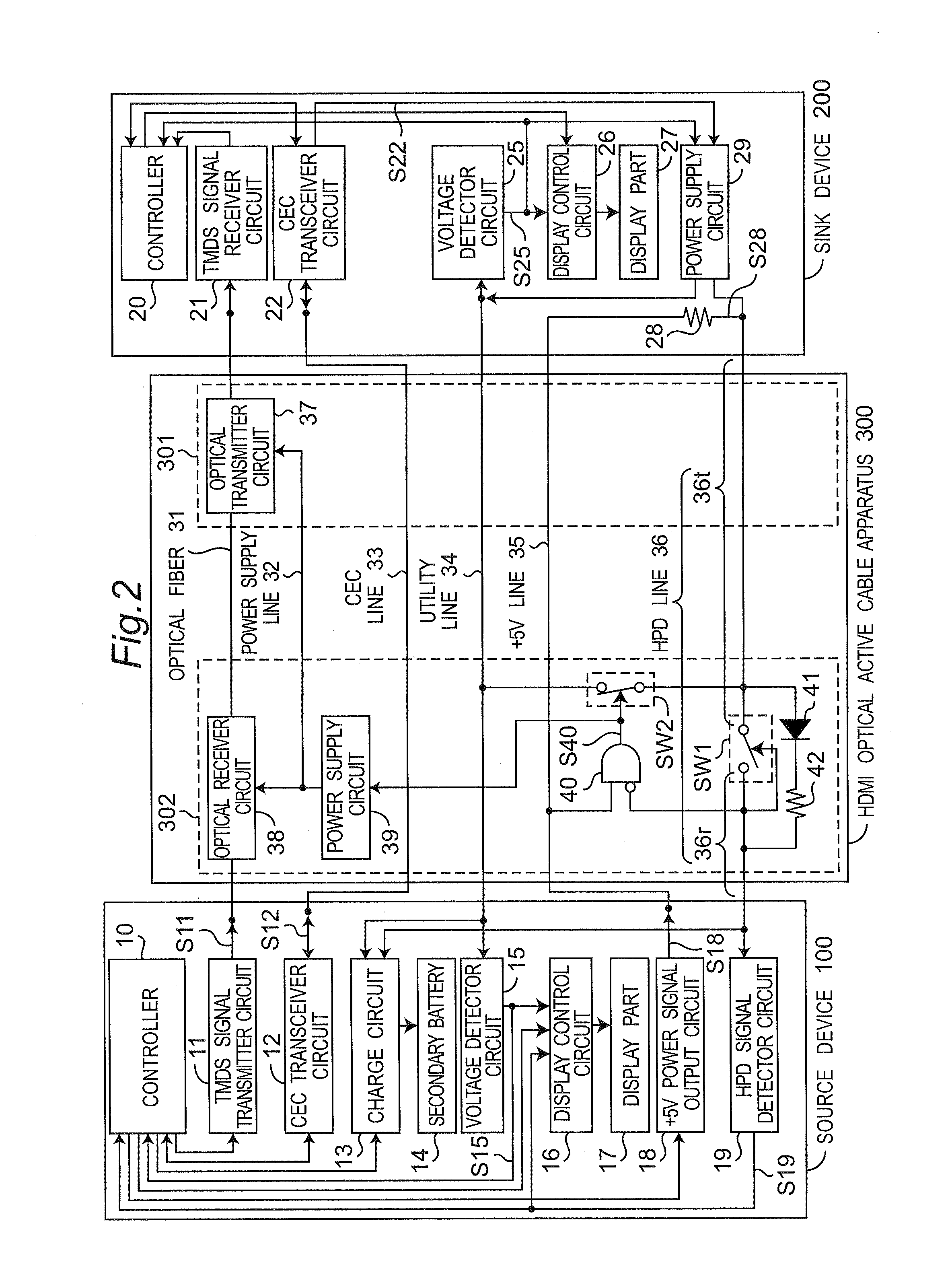
[0054]FIG. 1 is a block diagram showing a configuration of a communication system according to the first embodiment of the present disclosure, when an HDMI optical active cable apparatus 300 is correctly connected between a source device 100 and a sink device 200. In addition, FIG. 2 is a block diagram showing the communication system of FIG. 1 when the HDMI optical active cable apparatus 300 is reversely connected between the source device 100 and the sink device 200. Referring to FIG. 1, the communication system of the present embodiment is configured to include the source device 100 of a transmitter apparatus, the sink device 200 of a receiver apparatus, and the HDMI optical active cable apparatus 300 of a communication cable apparatus for connecting the source device 100 with the sink device 200.

[0055]Referring to FIG. 1, the source device 100 is, for example, a portable telephone, and is configured to include a controller 10, a TMDS (Transition Minimized Differential Signaling)...

second embodiment

[0094]FIG. 6 is a block diagram showing a configuration of a communication system according to the second embodiment of the present disclosure, when an HDMI optical active cable apparatus 300A is reversely connected between the source device 100 and the sink device 200. The communication system of FIG. 6 is different from the communication system of the first embodiment only in a point that the HDMI optical active cable apparatus 300A is provided instead of the HDMI optical active cable apparatus 300. Only differences between the present embodiment and the first embodiment are described hereinafter.

[0095]Referring to FIG. 6, the HDMI optical active cable apparatus 300A is different from the HDMI optical active cable apparatus 300 only in a point that a sink device connector 302A is provided instead of the sink device connector 302. The sink device connector 302A has a switch SW3 connected between the utility line 34 and the +5V line 35 instead of the switch SW2 as compared with the ...

third embodiment

[0099]FIG. 7 is a block diagram showing a configuration of a communication system according to the third embodiment of the present disclosure, when an HDMI optical active cable apparatus 300B is reversely connected between the source device 100 and the sink device 200. The communication system of FIG. 7 is different from the communication system of the first embodiment only in a point that an HDMI optical active cable apparatus 300B is provided instead of the HDMI optical active cable apparatus 300. Only differences between the present embodiment and the first embodiment are described hereinafter.

[0100]Referring to FIG. 7, the HDMI optical active cable apparatus 300B is different from the HDMI optical active cable apparatus 300 only in a point that a sink device connector 302B is provided instead of the sink device connector 302. The sink device connector 302B is different from the sink device connector 302 only in a point that a light-emitting diode 43 and a resistor 44 are provide...


PUM


Abstract

A switch is inserted and connected between a first portion and a second portion of an HPD line. The switch connects the first portion to the second portion when an HPD signal is outputted to the second portion. The switch cuts off the connection between the first portion and the second portion when the HPD signal is not outputted to the second portion. An AND gate generates a connection state detection signal that represents the connection state of an HDMI optical active cable, and outputs the connection state detection signal to a switch.

Description

CROSS-REFERENCE TO RELATED APPLICATIONS[0001]This is a continuation application of International application No. PCT / JP2012 / 006442, with an international filing date of Oct. 5, 2012, which claims priority to Japanese patent application No. JP 2011-284892 as filed on Dec. 27, 2011, the content of which is incorporated herein by reference.BACKGROUND[0002]1. Technical Field[0003]The present disclosure relates to a communication cable apparatus, a transmitter apparatus, a receiver apparatus, and a communication system. In particular, the present disclosure relates to a communication cable apparatus configured to transmit a data signal in a predetermined one direction from a transmitter apparatus to a receiver apparatus, the transmitter apparatus and the receiver apparatus connected to both ends of the communication cable apparatus, respectively, and a communication system that includes the transmitter apparatus, the communication cable apparatus and the receiver apparatus.[0004]2. Descr...

Claims


Application Information

Patent Timeline
IPC IPC(8): H04B10/25G02B6/28
CPCH04B10/25G02B6/28
Inventor NIIHO, TSUTOMUSHIBATA, OSAMUSAITO, YOSHIYUKI
Owner PANASONIC INTELLECTUAL PROPERTY MANAGEMENT CO LTD
Why Eureka
Try Eureka