Microfluidic device, microfluidic dosing system and method for microfluidic flow measurement and dosing

a microfluidic and microfluidic technology, applied in the direction of analytical using chemical indicators, laboratory glassware, instruments, etc., can solve the problems of insufficient dosing precision of micromembrane pumps, inability to achieve sufficient dosing precision when dosing minute volume quantities, etc., to achieve the effect of increasing the volume/length form factor of the channel, increasing the resolution of measurement, and increasing the accuracy of flow measuremen

Active Publication Date: 2013-07-18
FRAUNHOFER GESELLSCHAFT ZUR FOERDERUNG DER ANGEWANDTEN FORSCHUNG EV
View PDF14 Cites 34 Cited by
  • Summary
  • Abstract
  • Description
  • Claims
  • Application Information

AI Technical Summary

Benefits of technology

[0021]Another advantage of the invention is the fact that by reducing the channel dimensions (cross section, especially channel height) the measurement resolution can be increased significantly. E.g., if the height h of the measurement channel is reduced, the measurement signal per length of a capacitive measurement method will be increased (capacitance C˜1 / h), and the volume / length form factor of the channel will be decreased. For this two reasons, the flow measure accuracy is increasing at low flow rates.
is the fact that by reducing the channel dimensions (cross section, especially channel height) the measurement resolution can be increased significantly. E.g., if the height h of the measurement channel is reduced, the measurement signal per length of a capacitive measurement method will be increased (capacitance C˜1 / h), and the volume / length form factor of the channel will be decreased. For this two reasons, the flow measure accuracy is increasing at low flow rates.

Problems solved by technology

At present, micromembrane pumps, the functional principle of which is based on deflecting a membrane or diaphragm, are generally not able to achieve sufficient dosing precision when dosing minute volume quantities, such as, for example, 1 nl (nanoliter) to 100 μl (microliters).
Apart from the insufficient dosing precision of micromembrane pumps available at present, there are no systems, which may be implemented in an uncomplicated and thus cheap manner, to allow dosing and monitoring dosing of minute fluid quantities or fluid volumes in the nanoliter to microliter range.
In addition, flow sensors, easy to implement, for the smallest volume packages in the nanoliter range have not been available up to now, or they do not have the accuracy needed for many applications, or are too expensive to integrate into the microdosing system.

Method used


Image

  • Microfluidic device, microfluidic dosing system and method for microfluidic flow measurement and dosing
  • Microfluidic device, microfluidic dosing system and method for microfluidic flow measurement and dosing
  • Microfluidic device, microfluidic dosing system and method for microfluidic flow measurement and dosing

Examples


Embodiment Construction

[0032]Before discussing the present invention in further detail using the drawings, it is pointed out that in the figures identical elements, elements having the same function or the same effect are provided with same reference numerals so that the description of these elements and the functionality thereof illustrated in the different embodiments is mutually exchangeable or may be applied to one another in the different embodiments.

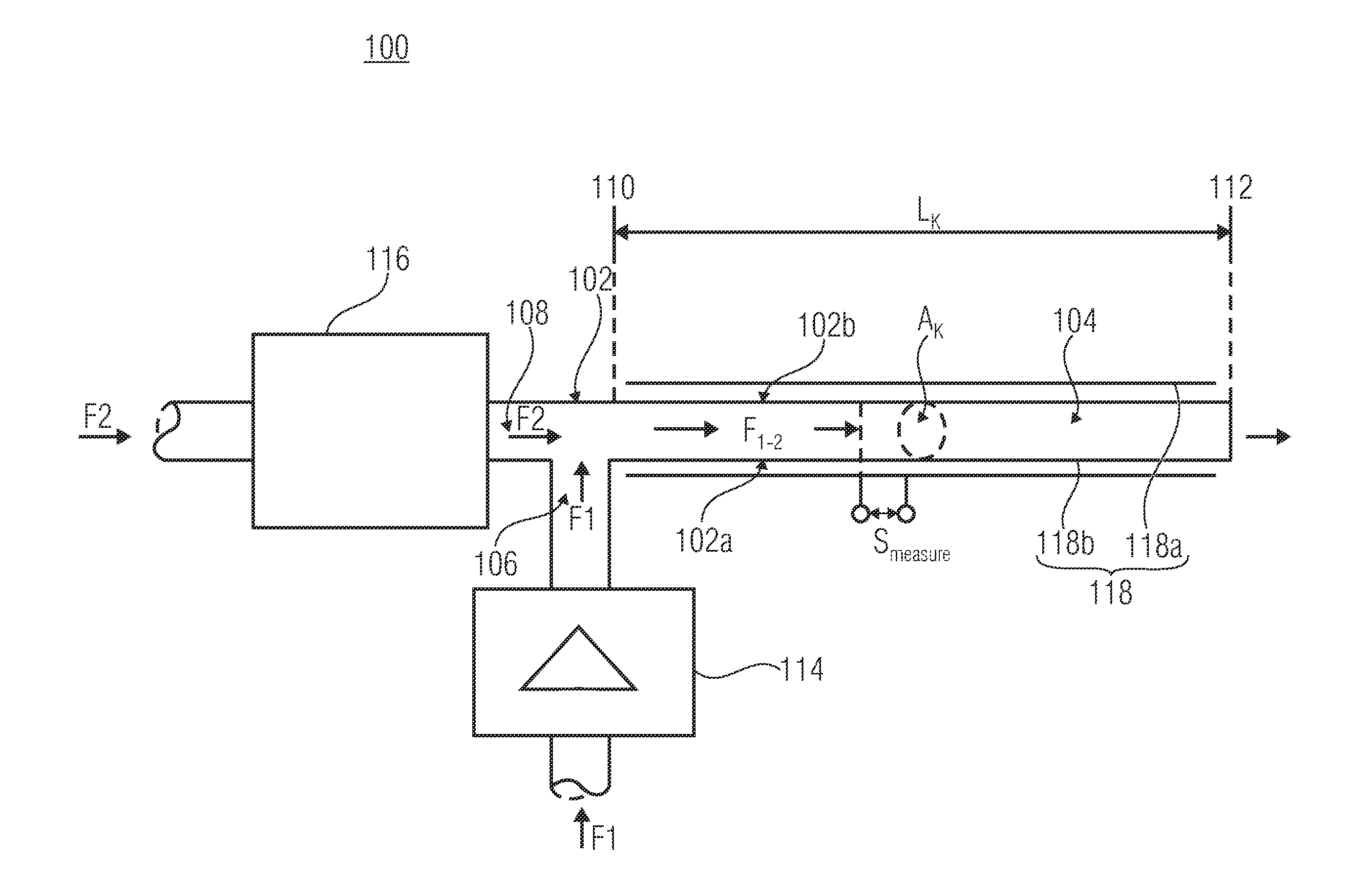
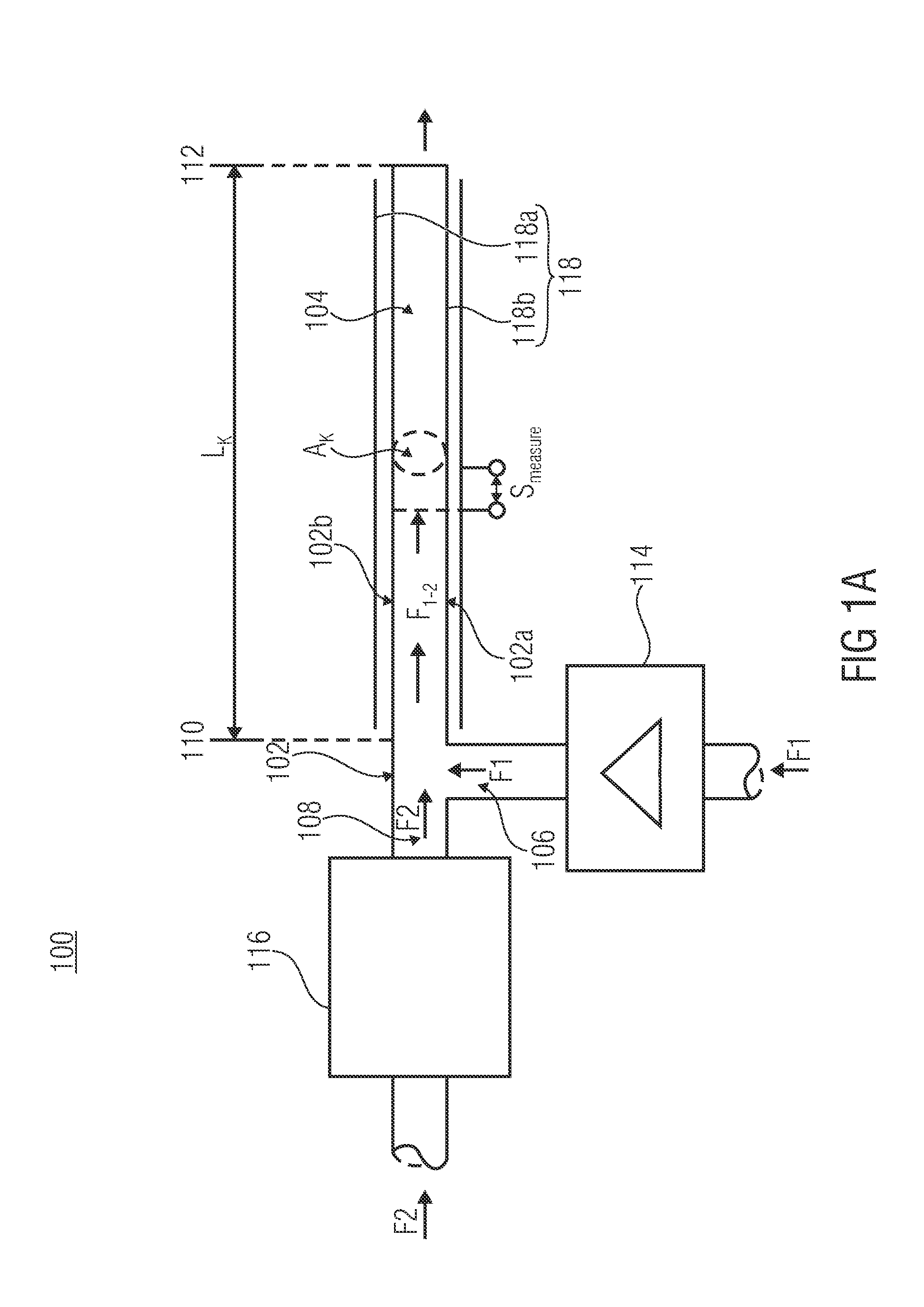
[0033]Subsequently, a first general embodiment of an inventive microfluidic device 100 for detecting a flow or stream parameter or dosing parameter will be described using FIG. 1a for a general discussion of the functional context.

[0034]As is depicted in FIG. 1a, the microfluidic device includes a channel 104 formed in a base body 102. On the input side, the channel 104 comprises a first inlet 106 for feeding a first fluid F1 and a second inlet 108 for feeding a second fluid F2 into a fluid input 112 so as to form a fluid stream F1-2 comprising the first...


PUM

PropertyMeasurementUnit
volumeaaaaaaaaaa
stroke volumesaaaaaaaaaa
diametersaaaaaaaaaa

Abstract

A microfluidic device for detecting a flow parameter, includes a channel configured within a base body, the channel including a first inlet for feeding a first fluid and a second inlet for feeding a second fluid so as to form a fluid stream having the first and second fluids within the channel, and further including an output for providing the fluid stream on the output side, a first feeder including a micropump associated with the first inlet for selectively feeding the first fluid to the channel, a second feeder associated with the second inlet for feeding the second fluid to the channel; and a detector for detecting, on the basis of a different physical property of the first fluid and the second fluid within the channel, a measurement value dependent on a current flow parameter of the first or second fluid.

Description

CROSS-REFERENCE TO RELATED APPLICATIONS[0001]This application is a continuation of copending International Application No. PCT / EP2010 / 063255, filed Sep. 9, 2010, which is incorporated herein by reference in its entirety.BACKGROUND OF THE INVENTION[0002]The present invention relates to a microfluidic device for detecting a flow parameter, a microfluidic dosing system, a method for detecting a flow parameter of a fluid stream within a channel and to a method for microfluidically dosing a fluid. In particular, the present invention relates to a microdosing concept for dosing minute quantities of fluids, such as, for example, quantities of a liquid or gas, within a fluid channel.[0003]In the field of medical technology, but also in other fields of technology, there is demand for dosing minute quantities or volumes of fluids (exemplarily in the range of nanoliters to microliters) with sufficient precision, and additionally also for being able to monitor this precise dosing process in ter...

Claims


Application Information

Patent Timeline
Patent Type & Authority Applications(United States)
IPC IPC(8): G01F1/58G01N21/17
CPCA61M5/14276G01F1/588A61M5/16827A61M5/16877A61M5/16886B01L3/502784B01L2200/0605B01L2200/0673B01L2200/14B01L2300/0627B01L2300/0681B01L2300/0867B01L2300/0877B01L2300/0887A61M5/16804B01L3/502761B01L3/502776B01F33/3021
Inventor RICHTER, MARTINKIBLER, SEBASTIAN
Owner FRAUNHOFER GESELLSCHAFT ZUR FOERDERUNG DER ANGEWANDTEN FORSCHUNG EV
Why Eureka
Try Eureka