
Partial joint resurfacing implant, instrumentation, and method

Active Publication Date: 2013-07-18
BIOPOLY
View PDF18 Cites 27 Cited by
  • Summary
  • Abstract
  • Description
  • Claims
  • Application Information

AI Technical Summary

Benefits of technology

The present invention is a system and method for repairing damaged or diseased articular cartilage in joints. The system includes a partial resurfacing implant and surgical instruments for accurate placement. The implant has a top articulating portion and supporting plate that helps in the insertion of the implant. The method allows for unrestricted motion over the defect site while transferring load through the implant to the underlying bone. The invention improves the quality and accuracy of surgical repair of articular cartilage defects.

Problems solved by technology

This tissue is susceptible to damage or deterioration caused by excessive loading resulting in inflammation, pain, swelling, and joint dysfunction.
Unfortunately the biomechanical properties of this tissue is not equivalent to the original hyaline cartilage, and over time the repair tissue is prone to wear, many times resulting in osteoarthritis.
This procedure is technically difficult as the cored bone / cartilage plugs must be accurately placed to create the new contiguous articulating surface.
Leaving the surface of the plugs too high or low can significantly compromise the surgical outcome.
While clinical outcomes are reported to be similar to the above described techniques this procedure is extremely expensive, requires two surgeries (one of which is a challenging open procedure), and similar long rehabilitation schedule.
Unfortunately they have not shown clinical outcomes advantageous to the above described techniques.
These prosthetic devices require an invasive, technically demanding implantation procedure and a long, involved, and painful rehabilitation period.
Further, these devices are often larger than the defective tissue that needs to be replaced, so healthy bone and cartilage are sacrificed to accommodate the implants.
Albeit that modern UKR and TKR devices are much improved from early hinged knee prostheses, there is still a loss of joint kinematics as this normal tissue is removed.
Additionally, the lifetime of TKRs is limited by a variety of implant and patient-related factors resulting in many patients outliving their primary prosthetic device, thus requiring a more difficult revision TKR surgery.
This device has operative advantages over traditional knee prostheses; however, the opposing articular cartilage is prone to damage due to the large differences in material properties and is further exacerbated by any contour mismatching.
These metal implants have exhibited adverse effects on the cartilage against which they articulate causing erosion of the facing cartilage in several clinical studies.
Thus, merely matching the anatomical shape of the cartilage that is resurfaced is not enough to prevent damage of the facing cartilage by a metallic counterface.
These implants also caused erosion of the facing cartilage in vivo likely due to a mismatch in surface chemistry properties, (i.e. UHMWPE is hydrophobic and cartilage is hydrophilic).
Thus, lower modulus implants alone are not enough to prevent damage of the facing cartilage.

Method used


Image

  • Partial joint resurfacing implant, instrumentation, and method
  • Partial joint resurfacing implant, instrumentation, and method
  • Partial joint resurfacing implant, instrumentation, and method

Examples


Embodiment Construction

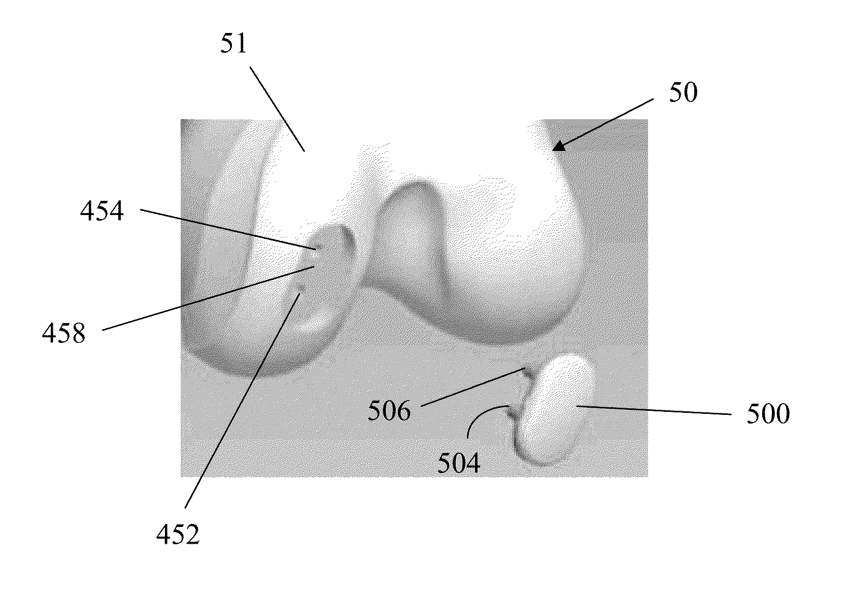
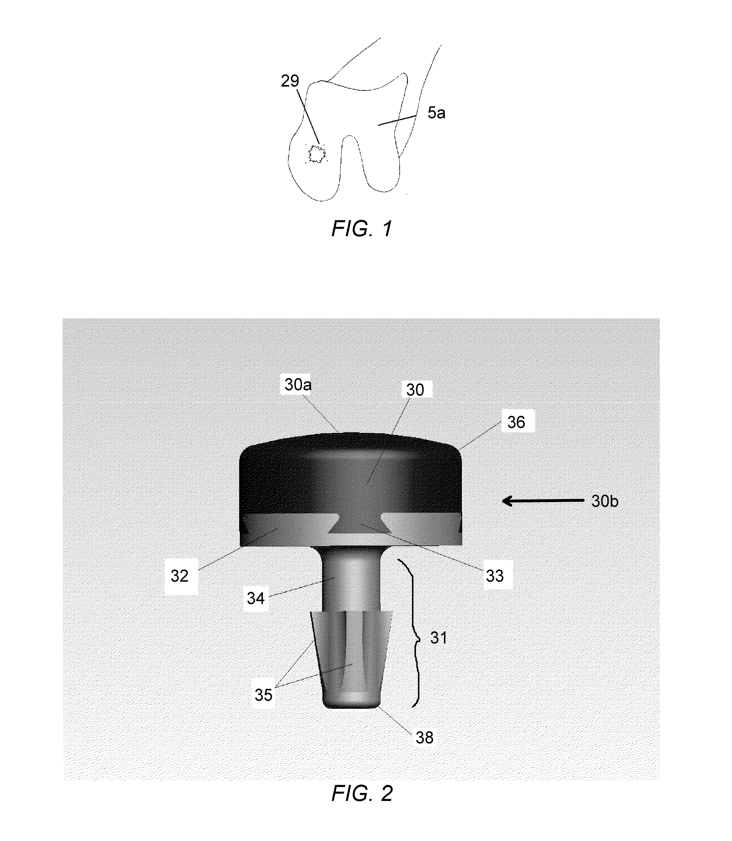
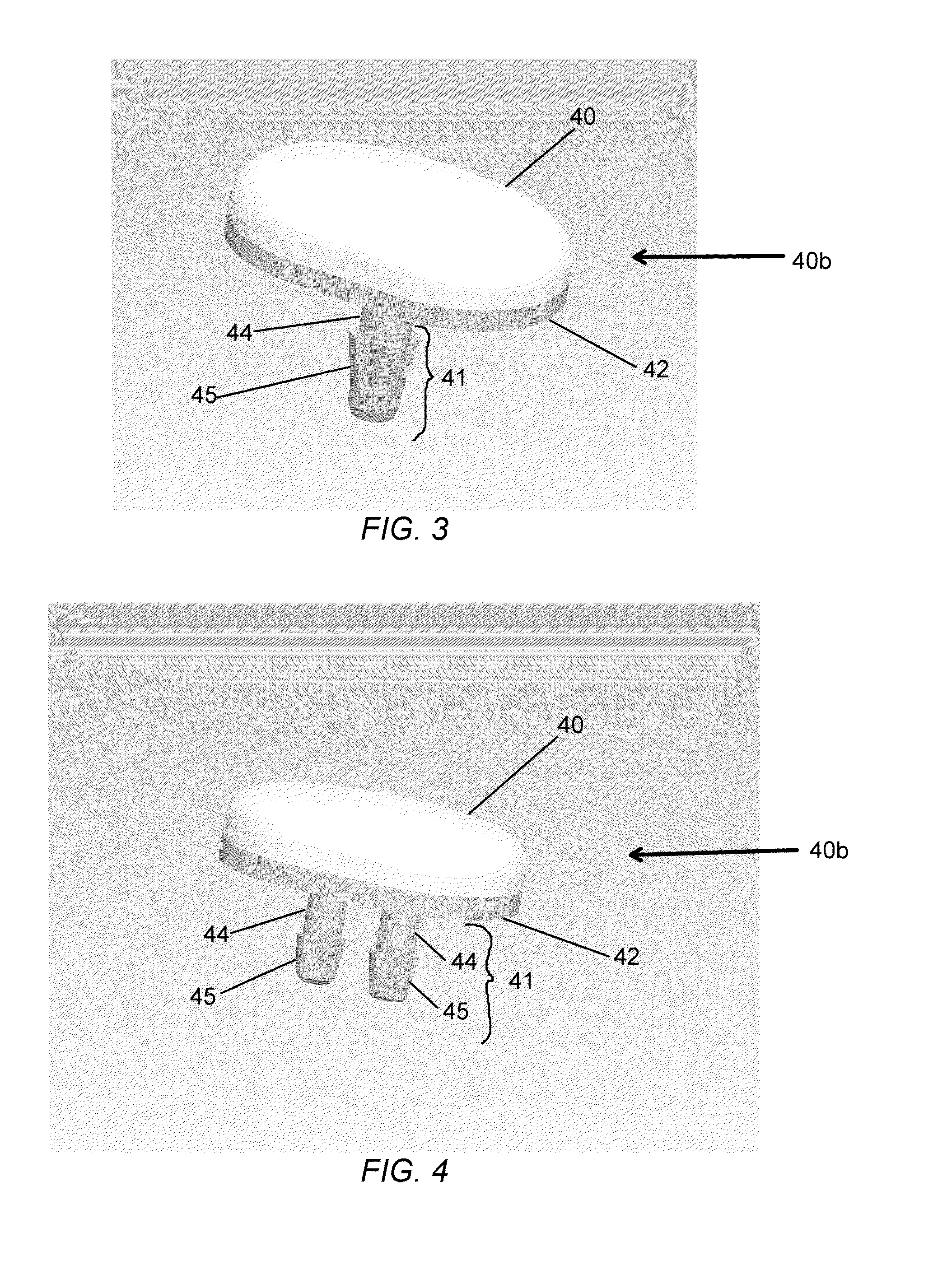
[0091]For the purposes of promoting an understanding of the principles of the partial joint resurfacing implant, corresponding surgical instruments and surgical method for inserting the resurfacing implant, reference will now be made to the embodiments, or examples, illustrated in the drawings and specific language will be used to describe these. It will nevertheless be understood that no limitation of the scope of the invention is thereby intended. Any alterations and further modifications in the described embodiments, and any further applications of the principles of the invention as described herein are contemplated as would normally occur to one skilled in the art to which the multi-functional surgical instrument invention relates.

[0092]In this detailed description and the following claims, the words proximal, distal, anterior, posterior, medial, lateral, superior and inferior are defined by their standard usage for indicating a particular part of a bone, prosthesis or surgical ...


PUM

PropertyMeasurementUnit
Sizeaaaaaaaaaa
Shapeaaaaaaaaaa
Radiusaaaaaaaaaa

Abstract

A method of repairing an articular cartilage defect with the partial joint resurfacing implant includes surgically creating an opening in the articular cartilage defect site. The method also includes obtaining a partial resurfacing implant which is implanted into the opening. The partial resurfacing implant includes a top articulating portion, an implant fixation portion, and a locking mechanism. The implant fixation portion including an upper segment coupled to the top articulating portion and a bone interfacing segment configured to facilitate insertion into the articular cartilage defect site. The method further includes the bone interfacing segment being inserted into the opening with the top articulating portion and adjacent articular cartilage being positioned to each other to facilitate motion and load transfer over the defect site. Another method of repairing an articular cartilage defect with a partial joint resurfacing implant and a partial joint resurfacing implant are also disclosed.

Description

CROSS-REFERENCE TO RELATED APPLICATION[0001]This application is a continuation-in-part application of U.S. application Ser. No. 12 / 919,607 filed Sep. 10, 2010, which is a national stage filing under section 371 of International Application No. PCT / US2009 / 034826 filed on Feb. 23, 2009 and published in English as WO 2009 / 108591 on Sep. 3, 2009 and claims priority to U.S. Provisional Application No. 61 / 032,141 filed Feb. 28, 2008, the entire disclosure of these applications being hereby incorporated herein by reference.TECHNICAL FIELD[0002]The present invention relates generally to surgical devices for use in partial resurfacing of damaged or diseased articular cartilage of the joints and to surgical methods using such devices.BACKGROUND OF THE INVENTION[0003]Articular cartilage, or hyaline type cartilage, is a unique tissue providing a smooth, lubricious, hydrophilic, load bearing covering on the ends of bones in diarthroidal joints, in particular the knee, hip, shoulder, to name a fe...

Claims


Application Information

Patent Timeline
IPC IPC(8): A61F2/30
CPCA61F2/30756A61F2310/00976A61B17/1635A61B17/1675A61B17/1764A61F2/4618A61F2/4684A61F2002/30014A61F2002/30065A61F2002/30112A61F2002/30125A61F2002/30224A61F2002/30299A61F2002/30327A61F2002/30331A61F2002/30387A61F2002/30759A61F2002/3085A61F2002/30878A61F2002/30884A61F2002/3096A61F2002/4662A61F2002/4685A61F2310/00407A61F2310/00796A61F2/4657A61B2090/062A61F2002/30766A61F2002/30329A61B17/1615A61B17/17A61F2/30771A61F2002/30326
Inventor SCHWARTZ, HERBERT E.PROCH, FRANCIS S.CONNER, NATHANAEL K.
Owner BIOPOLY
Learn More