
Transmission apparatus and transmission method

a transmission apparatus and transmission method technology, applied in the field of transmission apparatus and transmission method, can solve the problems of limited number of sessions connectable at a time, inability to know the subsequent state of the server, and inability to know the state of the server in real time by clients not actually connected to the server, so as to improve the equality of distributing stream data

Active Publication Date: 2013-07-18
CANON KK
View PDF4 Cites 2 Cited by
  • Summary
  • Abstract
  • Description
  • Claims
  • Application Information

AI Technical Summary

Benefits of technology

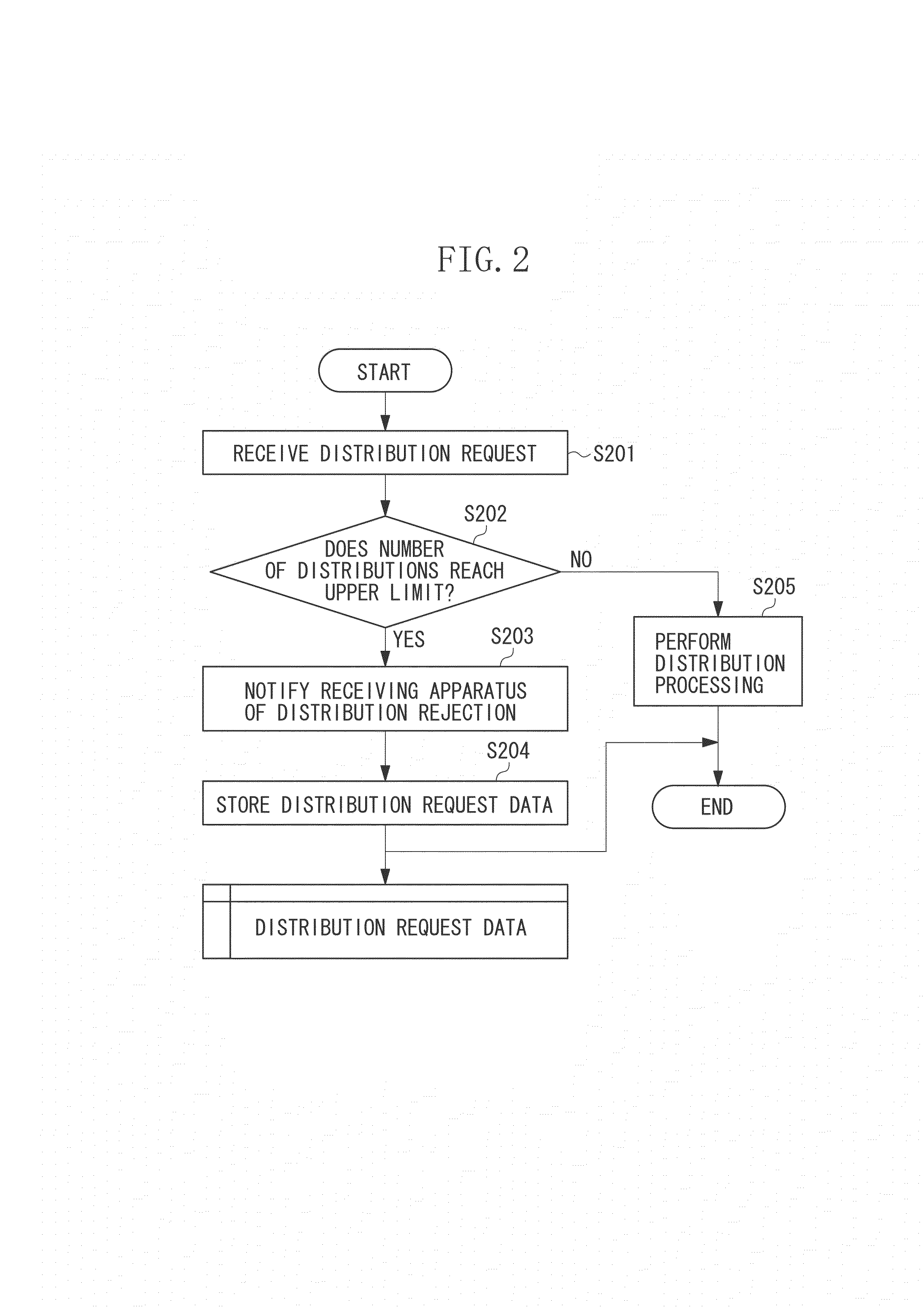
The present invention is about a transmission device that improves the distribution of data by avoiding unnecessary connections. It includes a mechanism for establishing a state where data can be transmitted to a receiver and receiving a transmission request from the receiver. If the number of times the data is transmitted is equal to or higher than a predetermined number, the device does not transmit the data to the receiver but keeps the state where it can be transmitted. If the number of times the data is transmitted is lower than the predetermined number, the device permits the data to be transmitted to the receiver. This mechanism ensures equal distribution of data and prevents overloading the network.

Problems solved by technology

The number of sessions connectable at a time is limited because of, for example, an issue of a resource of the server which distributes stream data and an issue of a communication band of a network.
Therefore, the client cannot know the subsequent state of the server.
However, a client not actually in connection with the server cannot know the state of the server in real time.
Therefore, in order to confirm whether the client can connect to the server, in some cases, the client may waste time in attempting to connect to the server many times or may miss a right timing to connect to the server.

Method used


Image

  • Transmission apparatus and transmission method
  • Transmission apparatus and transmission method
  • Transmission apparatus and transmission method

Examples


Embodiment Construction

[0023]Various exemplary embodiments, features, and aspects of the invention will be described in detail below with reference to the drawings.

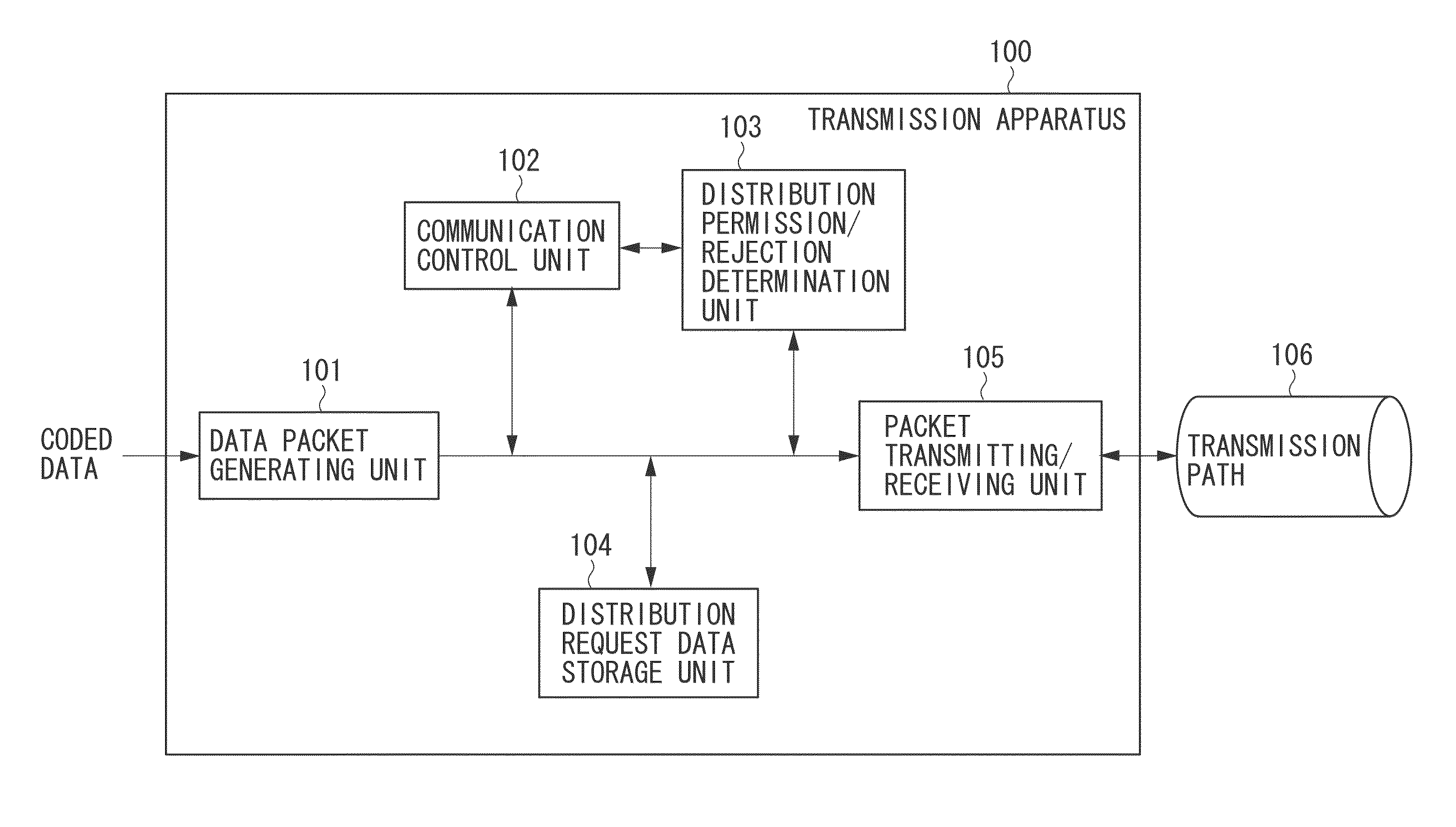
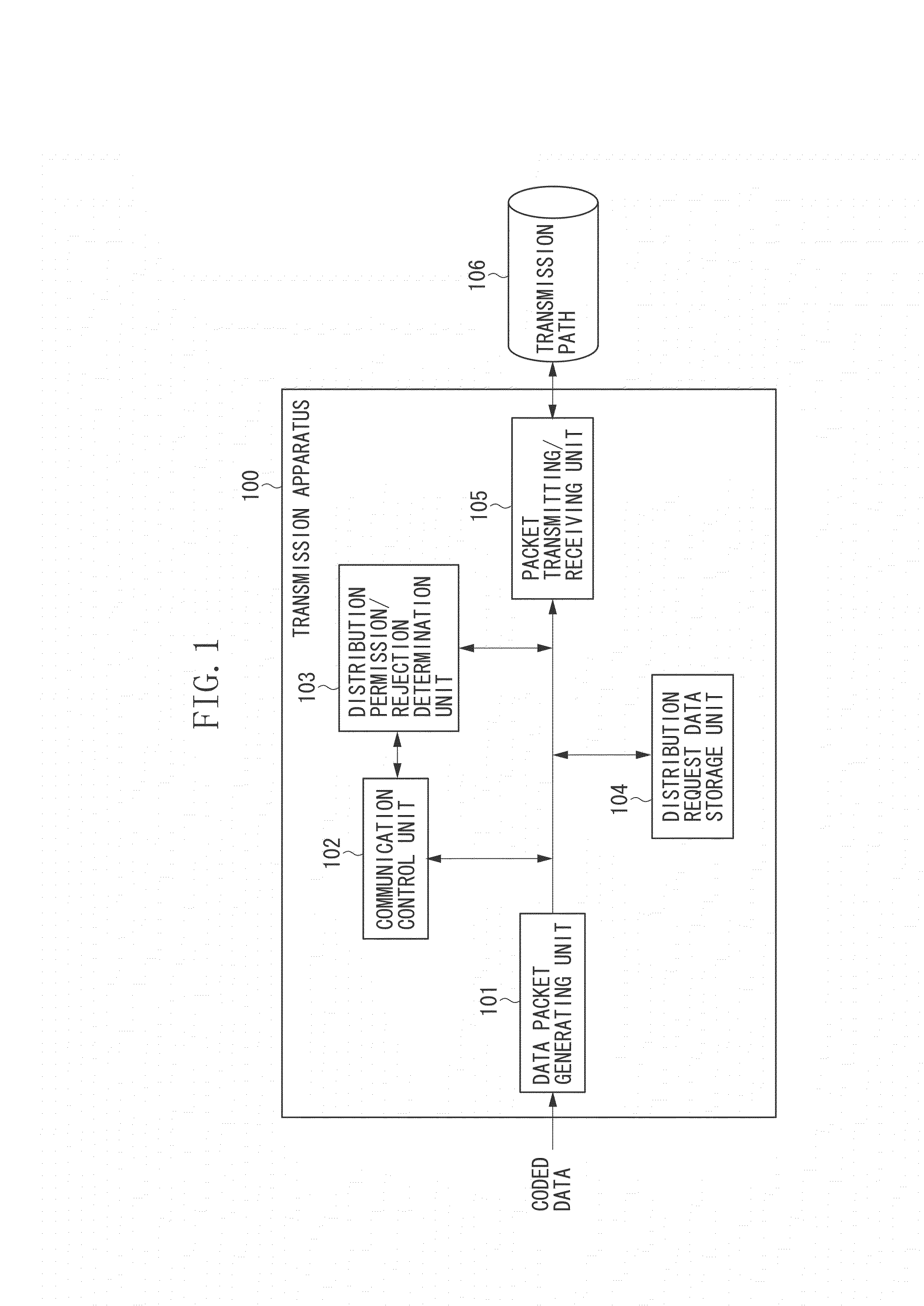
[0024]A configuration of a computer apparatus constituting a transmission apparatus according to the present exemplary embodiment of the present invention is described below with reference to a block diagram in FIG. 1. The transmission apparatus and a receiving apparatus may be realized with an independent single computer or may be realized with a plurality of computer apparatuses having different functions shared therebetween as required. In a case where the transmission apparatus and the receiving apparatus includes the plurality of computer apparatuses, the plurality of computer apparatuses are connected to each other via a local area network (LAN) so as to be able to communicate with each other.

[0025]In FIG. 1, a transmission apparatus 100 includes a data packet generating unit 101, a communication control unit 102, a distribution permissio...


PUM


Abstract

A transmission apparatus for transmitting content data to a receiving apparatus includes an establishing unit configured to establish a state where the content data can be transmitted to the receiving apparatus, a reception unit configured to receive a transmission request of the content data from the receiving apparatus in the established state where the content data can be transmitted, and a control unit configured to perform control such that, while a number of transmissions of the content data is equal to or greater than a predetermined number, the control unit does not transmit the content data to the receiving apparatus having issued the transmission request but keeps the state where the content data can be transmitted to the receiving apparatus and, when the number of transmissions of the content data becomes less than the predetermined number, the control unit permits the content data to be transmitted to the receiving apparatus.

Description

BACKGROUND OF THE INVENTION[0001]1. Field of the Invention[0002]The present invention relates to a transmission apparatus and a transmission method, and more specifically, to a technology capable of transmitting data more equally and efficiently in a case where the number of data distributions is limited.[0003]2. Description of the Related Art[0004]Recently, there has been utilized a technology in which multimedia data such as video and audio is streamed via an IP network in order to view the video and listen to the audio. More specifically, when distributing the multimedia data that requires real-time distribution, e.g., live video, a communication protocol, which is referred to as Real-time Transport Protocol (RTP), is generally used.[0005]RTP is a protocol for transferring data, e.g., mainly audio and video, in real time and is defined as RFC3550 by Internet Engineering Task Force (IETF). RTP is an upper protocol of User Datagram Protocol (UDP), which is a non-connection type pro...

Claims


Application Information

Patent Timeline
Patent Type & Authority Applications(United States)
IPC IPC(8): H04L29/08
CPCH04L67/02H04L65/1069H04L65/4092H04L65/00H04N21/2396H04N21/6437H04L65/80H04L65/613
Inventor SUNEYA, TORU
Owner CANON KK
Learn More