Punching apparatus and method

Inactive Publication Date: 2013-07-25
HONDA MOTOR CO LTD
View PDF2 Cites 9 Cited by
  • Summary
  • Abstract
  • Description
  • Claims
  • Application Information

AI Technical Summary

Benefits of technology

[0018]The method has an advantage that the only one step of punching the sheet 22 c

Problems solved by technology

This would result in variation in thickn

Method used


Image

  • Punching apparatus and method
  • Punching apparatus and method
  • Punching apparatus and method

Examples


Embodiment Construction

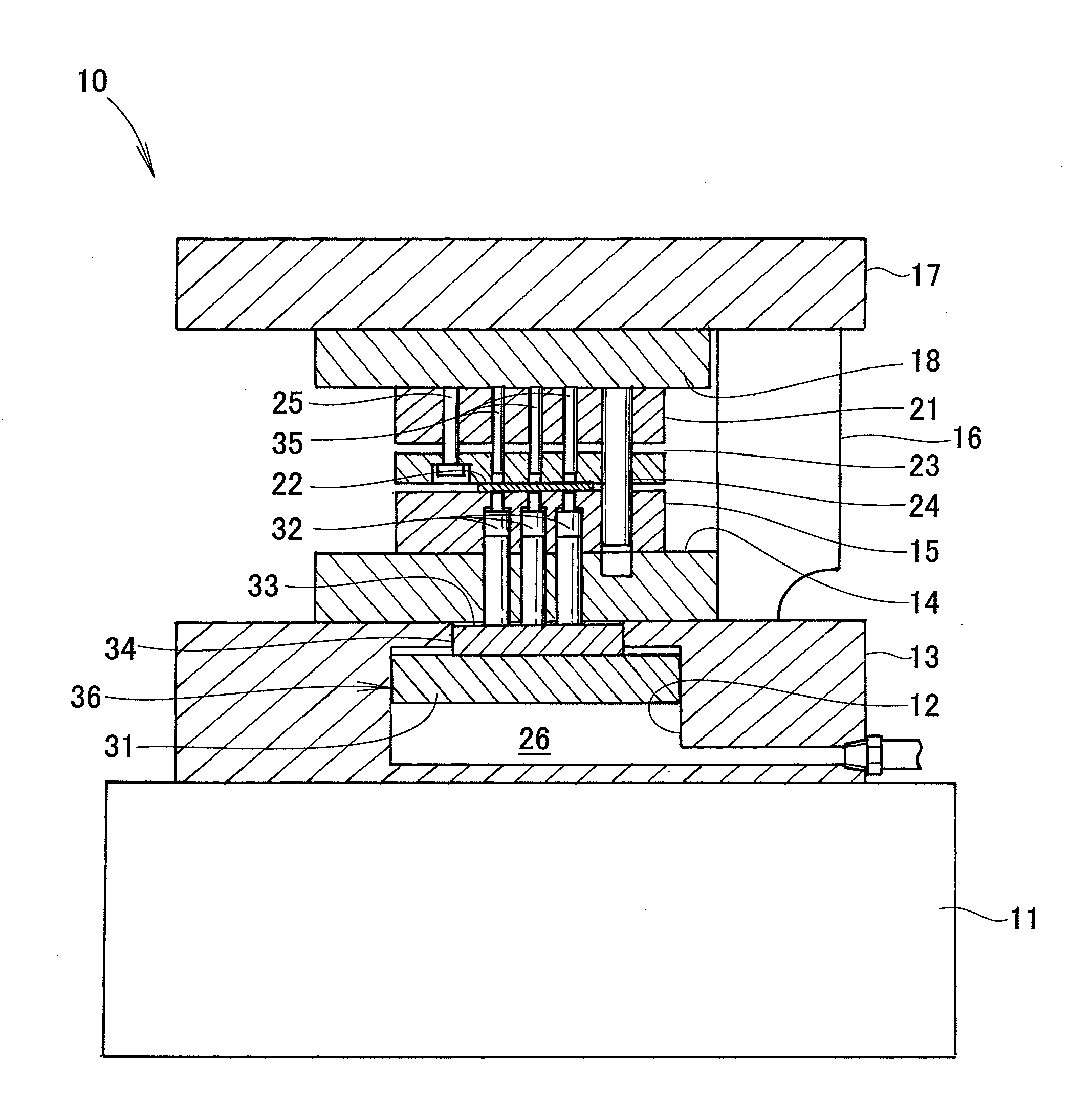
[0028]As shown in FIG. 1, a workpiece-punching apparatus 10 in one embodiment of the present invention includes a base or bolster 11, and a lower die set 13 provided on a top of the bolster 11 and defining a hydraulic cylinder 12 therein. The apparatus 10 also includes a die plate 15 disposed above the lower die set 13 with a packing plate 14 provided therebetween. The apparatus 10 further includes an upper die set 17 actuated by a driver 16 to move vertically in opposed relation to the lower die set 13. The apparatus 10 further includes a punch plate 21 disposed the upper die set 17 with a packing plate 18 provided therebetween. The apparatus 10 further includes a vertically moveable upper die pad 23 disposed below the punch plate 21 for clamping a workpiece or metal sheet 22 from thereabove.

[0029]Attached to the packing plate 18 is a guide post 24 for guiding the punch plate 21 and the upper die pad 23 to the die plate 15. A retainer 25 is attached to the packing plate 18 for limi...


PUM

PropertyMeasurementUnit
Fractionaaaaaaaaaa
Diameteraaaaaaaaaa
Areaaaaaaaaaaa

Abstract

A punching apparatus includes a plurality of punches for punching a workpiece, a pad, and a single piston supporting the pad. The punches are disposed on a top surface of a portion of the pad. The top surface has a circumference circumscribing circumferences of outermost ones of the punches. A diameter of the piston is larger than a diameter of the portion of the pad.

Description

FIELD OF THE INVENTION[0001]The present invention relates to a punching apparatus and method for punching a workpiece.BACKGROUND OF THE INVENTION[0002]A workpiece-punching apparatus includes a plurality of punches for punching a workpiece or metal sheet, a pad supporting the punches, and a shaft for moving the pad between an advanced position and a retracted position, as disclosed in JP-A-11-254190.[0003]FIG. 8 hereof shows a workpiece-punching apparatus 101 disclosed in JP-A-11-254190. The punching apparatus 101 includes a table 102 and a bolster 103 provided on the table 102. The bolster 103 has a pad 105 vertically movably provided in an upper part thereof for supporting a plurality of punches 104. The pad 105 is fastened to a nut 106 of a ball screw. The ball screw includes a threaded shaft 107 rotationally provided in the upper part of the bolster 103. The shaft 107 engages the nut 106 with balls 108 being disposed in a groove formed between the shaft 107 and the nut 108. Rotat...

Claims


Application Information

Patent Timeline
IPC IPC(8): B21D28/00B21D28/02
CPCB21D28/002B21D28/02B30B1/007B21D28/06B21D53/14Y10T83/06Y10T83/8828
Inventor ONISHI, SHINSUKESHIN, UGEUNNAKAMURA, SHINTAROFUJITA, MASAAKIFUJIWARA, KAZUMA
Owner HONDA MOTOR CO LTD
Why Eureka
Try Eureka