
Intelligent fastener

a technology of intelligent fasteners and threads, applied in the direction of screws, load modified fasteners, instruments, etc., can solve the problems of inability to accurately measure the torque on a given, process is very time-consuming and subject to human error, and cannot always be done, so as to facilitate the installation and follow-up checking of the fastener

Active Publication Date: 2013-07-25
SILICON VALLEY MICRO C
View PDF3 Cites 48 Cited by
  • Summary
  • Abstract
  • Description
  • Claims
  • Application Information

AI Technical Summary

Benefits of technology

The invention provides a threaded fastener with intelligent properties that facilitates fastener installation and follow-up checking. The fastener can be automatically driven to the proper torque value and checked quickly after installation. The scanning inspection technique avoids the need to manually check the current value of each installed fastener, which reduces the time required for the inspection process to be conducted. The information provided in the form readable by the associated tag reader enables a complete history of the fastener installation project to be compiled and saved in a host computer for future maintenance purposes. The advantages of the invention are afforded at relatively low additional cost per fastener.

Problems solved by technology

However, this is not always done.
Because the inspection process must be manually and visually performed on each individual fastener, the process is very time consuming and subject to human error—e.g., by failing to correctly apply the proper torque specification value to one or more fasteners, failure to accurately measure the torque on a given fastener or failure to notice the absence of a fastener from a designated fastener site.
In addition, as noted above, a record of the initial installation of fasteners is not always created to the detriment of those responsible for maintaining the integrity and safety of fastened structures.

Method used


Image

  • Intelligent fastener
  • Intelligent fastener
  • Intelligent fastener

Examples


Embodiment Construction

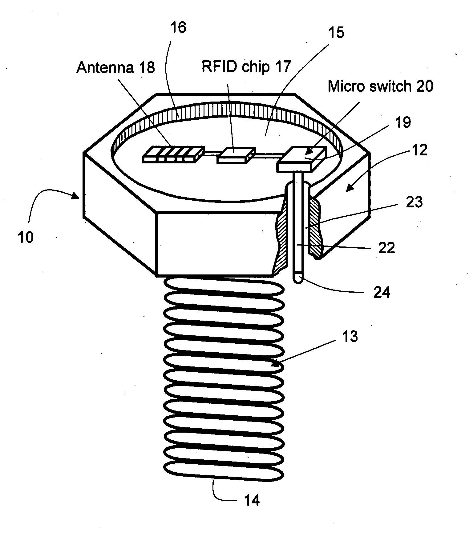
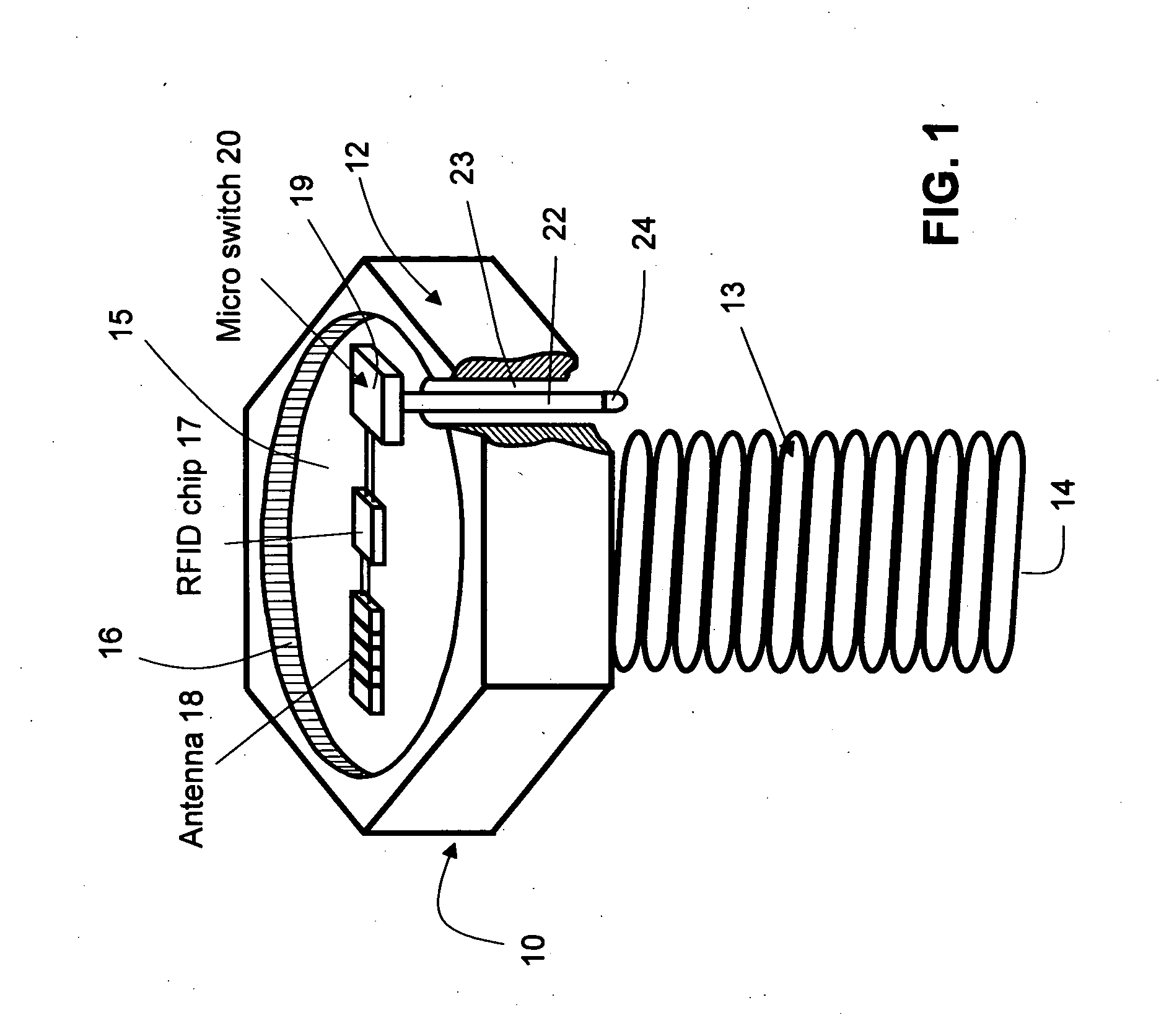
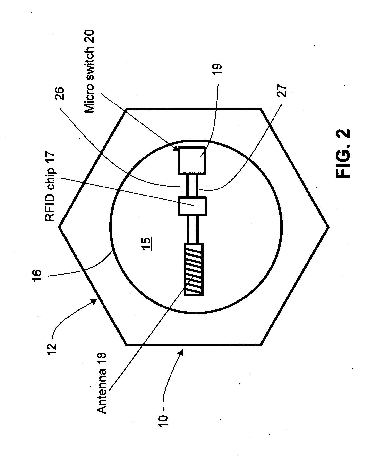
[0024]Turning now to the drawings, FIGS. 1 and 2 illustrate a single fastener according to the invention. As seen in these Figs., a fastener generally designated with reference numeral 10 has a head 12 and a threaded shank 13 terminating in a free end 14. Fastener head 12 has a central recess defined by a recessed upper surface 15 and a boundary wall 16 of sufficient depth and boundary dimensions to accommodate an RFID chip 17, an antenna 18 and an upper body portion 19 of a microswitch 20. Elements 17, 18, and 19 are all carried by recessed upper surface 15 of head 12. The remaining portion of microswitch 20 comprises a switch activating arm 22 which extends downwardly through a throughbore 23 formed in head 12 and terminates in a free end 24. The free end 24 of switch activating arm 22 terminates at a predetermined level below a lower surface 25 (shown in FIG. 4) of head 12 for a purpose described below. The relative diameter dimensions of throughbore 23 and switch activating arm ...


PUM


Abstract

An intelligent fastener having a head and an externally threaded shank for threaded engagement with a structural member. The head has a recess formed in the top surface for mounting an RFID tag with a memory containing information specific to the fastener—such as fastener identification, specified torque value and other information—an antenna for enabling bidirectional communication with an RFID tag reader, and a torque value sensor for determining the torque applied to the fastener by a fastener installation tool. Once installed, the existing torque on a collection of fasteners is measured by using an RFID tag reader to scan the information stored in the memory of each fastener.

Description

BACKGROUND OF THE INVENTION[0001]This invention relates to threaded fasteners. More particularly, this invention relates to industrial threaded fasteners having intelligent properties.[0002]Threaded fasteners have long been used to fasten together myriad types of mechanical parts. Some examples of the different types of mechanical parts which can be fastened together by threaded fasteners are structural members, such as bridge girders, support beams in buildings, and aircraft structural members. Typically, during installation each threaded fastener is inserted into an aperture in the piece to be captured and threaded into a designated portion of the mating piece, such as a nut secured to, or a threaded aperture formed in, the mating piece. In many applications, each fastener must be threadably tightened to a specific torque amount within a narrow band of specified tolerances. The specified tolerances are usually part of the specifications created for a given project, and may be pres...

Claims


Application Information

Patent Timeline
Patent Type & Authority Applications(United States)
IPC IPC(8): G06K19/077G06F17/30
CPCG06K19/07779G06F17/30725F16B31/02F16B2031/022F16B5/02
Inventor ZHU, SHENGBOHUANG, SU SHIONG
Owner SILICON VALLEY MICRO C
Learn More