
LED lighting circuit capable of preventing thermal breakdown

a technology of led lighting and thermal breakdown, which is applied in the direction of lighting apparatus, electroluminescent light sources, light sources, etc., can solve the problems of affecting reducing the efficiency of led lighting circuits, so as to prevent a thermal breakdown of the controller and reduce the power dissipation of the controller. , the effect of preventing the controller from being damaged

Inactive Publication Date: 2013-07-25
IMMENSE ADVANCE TECH
View PDF0 Cites 7 Cited by
  • Summary
  • Abstract
  • Description
  • Claims
  • Application Information

AI Technical Summary

Benefits of technology

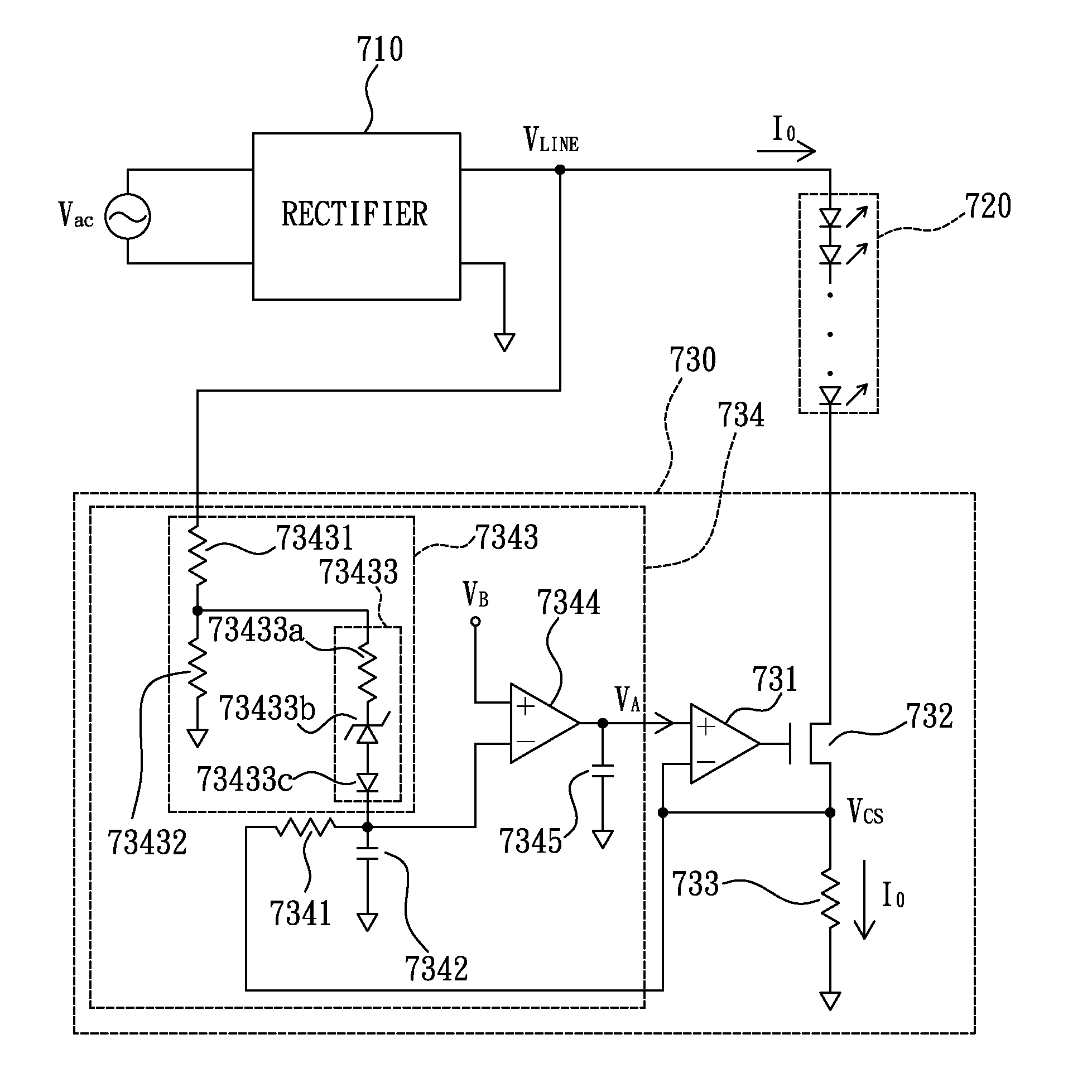
The present invention is proposing an LED lighting circuit that can reduce the power dissipation in a controller and prevent the controller from thermal breakdown at high levels of the line voltage. The LED lighting circuit includes a rectifier, an LED module, and a controller. The circuit generates an adjustable reference voltage that decreases with the increase of the line voltage after exceeding a threshold. This helps to reduce the current flowing through the LED module and prevent thermal breakdown of the controller.

Problems solved by technology

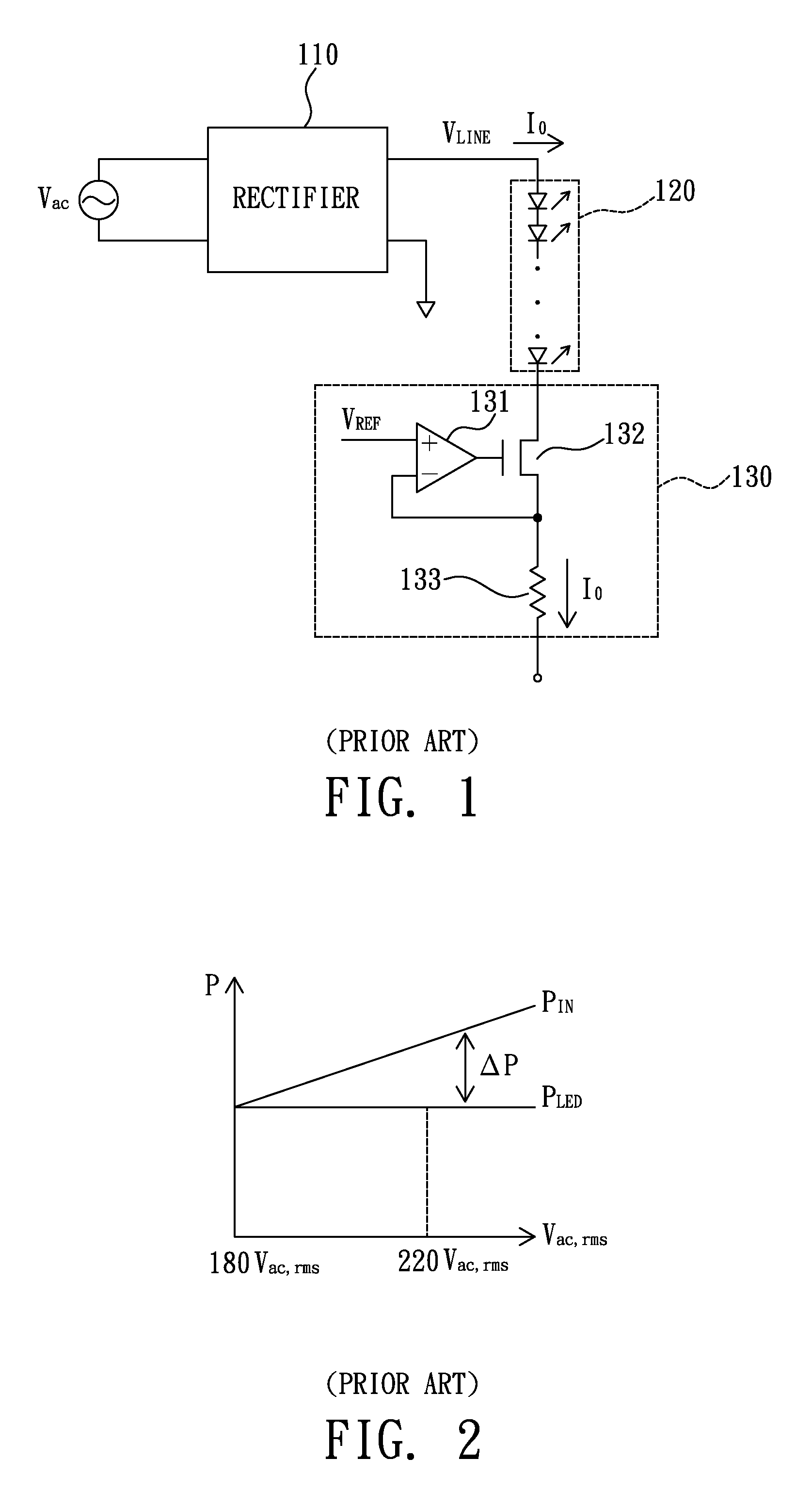
However, when the amplitude of the AC voltage Vac increases, the voltage across the controller 130 will increase accordingly, causing much power dissipated in the controller 130.
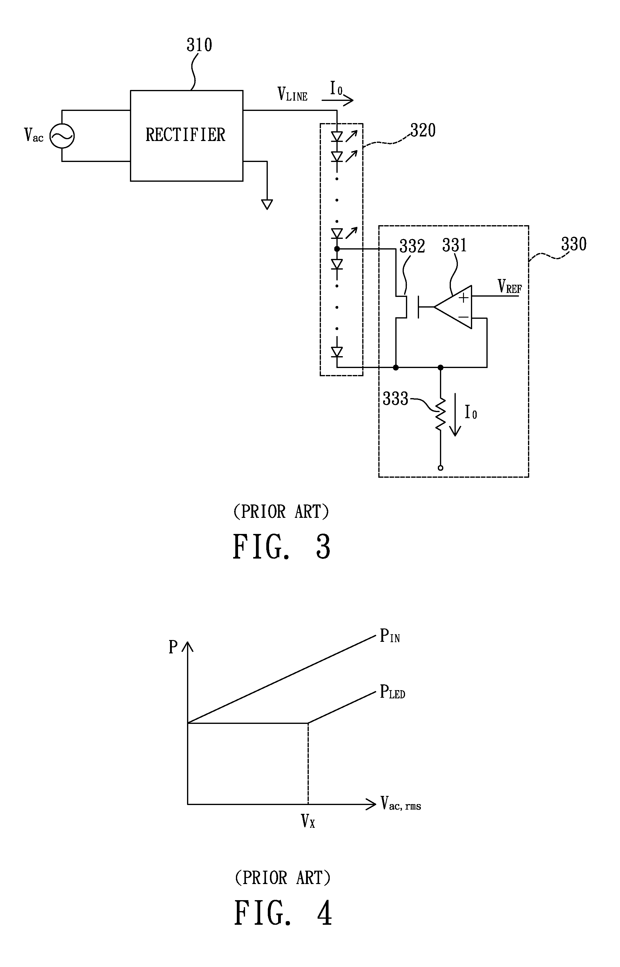
However, as the cost of the LED module 320 occupies a major portion of the LED lighting circuit, the including of the second plurality of LEDs into the LED module 320 will increase a lot of cost to the LED lighting circuit.

Method used


Image

  • LED lighting circuit capable of preventing thermal breakdown
  • LED lighting circuit capable of preventing thermal breakdown
  • LED lighting circuit capable of preventing thermal breakdown

Examples


Embodiment Construction

[0044]The present invention will be described in more detail hereinafter with reference to the accompanying drawings that show the preferred embodiments of the invention.

[0045]To prevent a thermal breakdown of an LED lighting circuit occurring at high root-mean-square values of an AC voltage, the present invention proposes a novel mechanism to decrease the power consumption in both the LED lighting circuit and an LED module therein after the root-mean-square value of the AC voltage exceeds a threshold.

[0046]Please refer to FIG. 5, which illustrates a profile of PIN (the power delivered into an LED lighting circuit) and a profile of PLED (the power dissipated in an LED module) over the root-mean-square value Vac,rms of an AC voltage Vac according to the present invention. As can be seen in FIG. 5, both PIN and PLED start to decrease with the increase of Vac,rms and the difference between PIN and PLED is bounded after Vac,rms exceeds a threshold voltage VX. By this arrangement, the he...


PUM


Abstract

An LED lighting circuit capable of preventing thermal breakdown, including: an LED module, having a top end coupled to a line voltage; and a controller, coupled to the line voltage and a bottom end of the LED module, the controller including: an amplifier, having a positive input end coupled to an adjustable reference voltage; a transistor, having a gate terminal coupled to an output end of the amplifier, a first channel terminal coupled to the bottom end of the LED module, and a second channel terminal coupled to a negative input end of the amplifier; a current sensing resistor, coupled between the second channel terminal and a ground; and a reference voltage generator, used for generating the adjustable reference voltage according to the line voltage.

Description

BACKGROUND OF THE INVENTION[0001]1. Field of the Invention[0002]The present invention relates to an LED (light emitting diode) lighting circuit, and more particularly to an LED lighting circuit capable of preventing a thermal breakdown caused by high line voltages.[0003]2. Description of the Related Art[0004]Please refer to FIG. 1, which illustrates a prior art LED lighting circuit. As illustrated in FIG. 1, the prior art LED lighting circuit includes a rectifier 110, an LED module 120, and a controller 130.[0005]The rectifier 110, usually a full-wave bridge rectifier, is used to rectify an AC voltage Vac to generate a line voltage VLINE.[0006]The LED module 120, including a plurality of LEDs connected in series, is powered by the line voltage VLINE.[0007]The controller 130, including an amplifier 131, an NMOS transistor 132, and a current sensing resistor 133, is connected between the LED module 120 and a ground to regulate an output current IO flowing through the LED module 120.[0...

Claims


Application Information

Patent Timeline
IPC IPC(8): H05B37/02
CPCH05B33/089H05B33/0824H05B45/44H05B47/28
Inventor LO, YUAN-HUNGSU, WEI-CHUANWANG, YEN-HUI
Owner IMMENSE ADVANCE TECH
Learn More