Monitoring for disturbance of optical fiber

Active Publication Date: 2013-07-25
NETWORK INTEGRITY SYST
View PDF2 Cites 34 Cited by
  • Summary
  • Abstract
  • Description
  • Claims
  • Application Information

AI Technical Summary

Benefits of technology

[0019]An object of the present invention is to at least mitigate deficiencies of such previous

Problems solved by technology

Such a low loss might be impossible to detect reliably by intrusion detection systems which use power measurement methods.
Although, on the face of it, such a detection procedure might seem straightforward, in practice it is difficult to differentiate between normally-occurring disturbances and abnormal or “reportable” disturbances which should be reported because, for example, they result from a genuine intrusion attempt.
The difficulty arises because effects in the fiber's environment can cause optical changes with similarities to some of those caused by intrusions.
In view of the time taken to acquire enough samples for analysis, this method is mainly suitable for detecting slow changes, and is poorer for characterizing activity such as bumps or rattling that are associated with preparations to tap a fiber or other intrusions that have faster changes characterized by variations at moderate acoustic frequencies.
The alignment is generally unpredictable depending on how different parts of the deployed fiber happen to be bent, twisted or stressed; and it will vary as environmental factors change (such as the temperature of the optical fiber cable).
This unpredictable and variable sensitivity can make it difficult or impossible to set a threshold that the observed magnitude of a disturb

Method used


Image

  • Monitoring for disturbance of optical fiber
  • Monitoring for disturbance of optical fiber
  • Monitoring for disturbance of optical fiber

Examples


embodiment 1

Two Launch States; Four Analyzer States

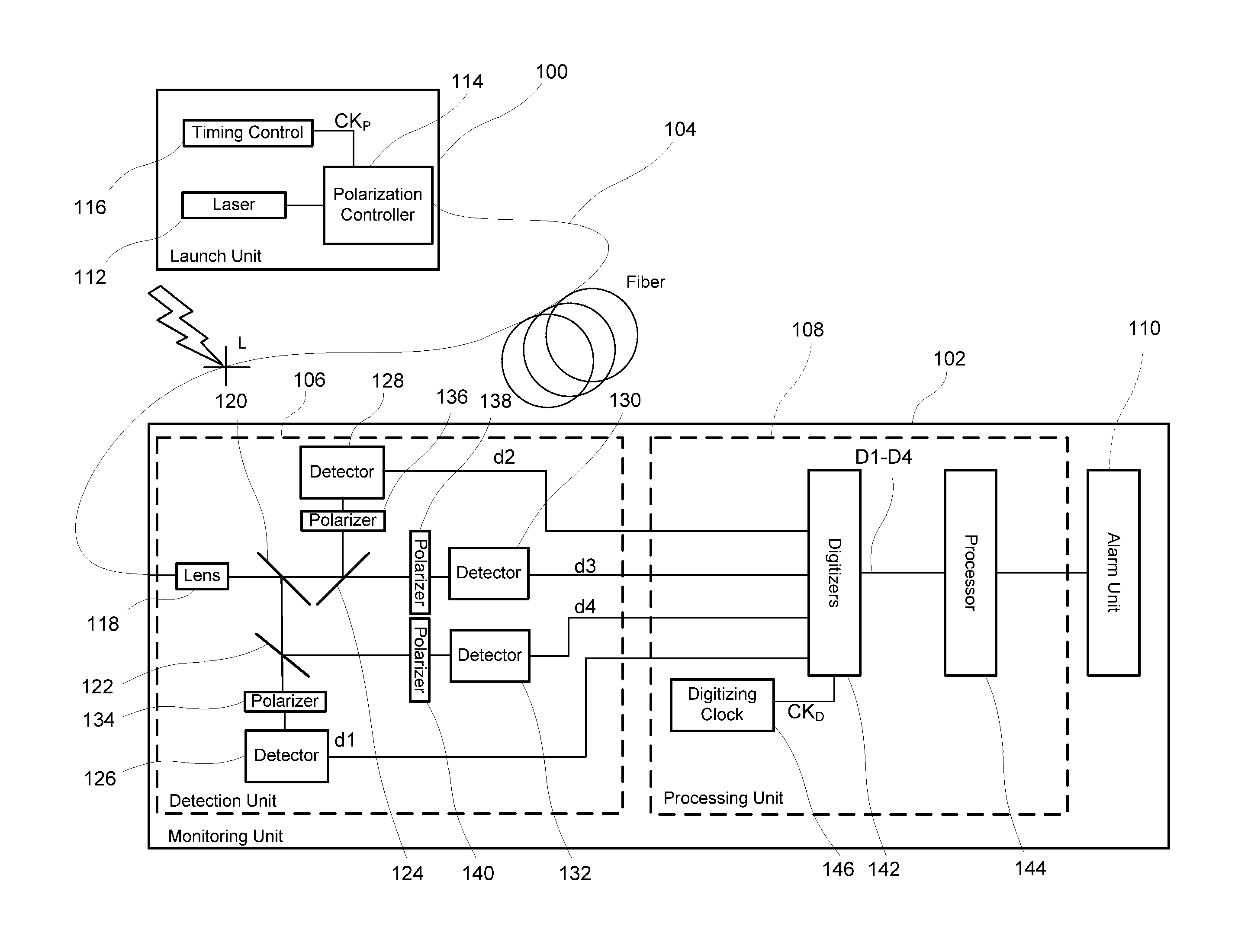
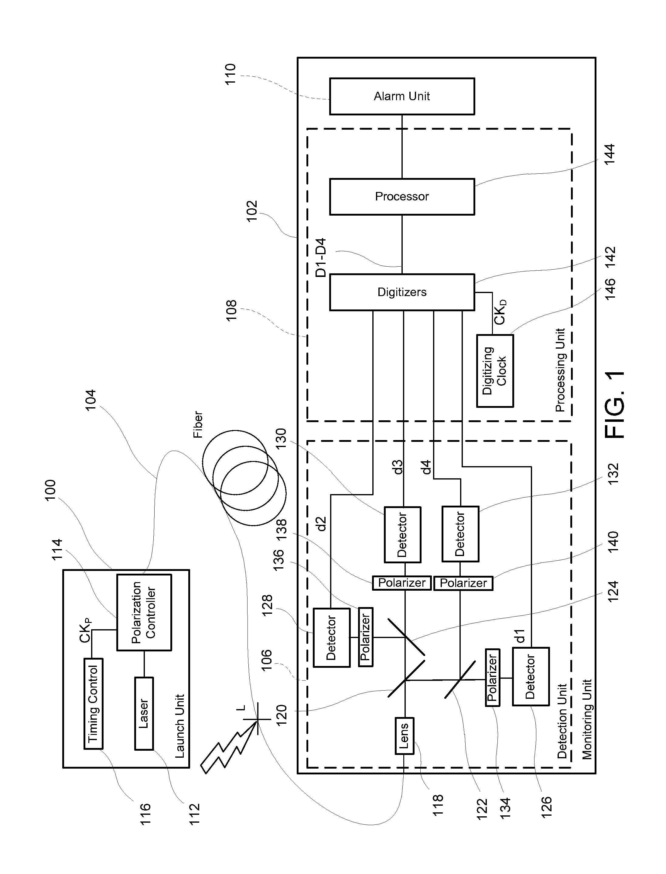
[0112]A first embodiment, a monitoring system that uses two launch states and four analyzer states, will be described by way of example with reference to FIGS. 1 to 15. As shown in FIG. 1, a launch unit 100 and a monitoring unit 102 are coupled to first and second ends, respectively, of a length of optical fiber 104 which might be from a few meters to more than 40 km long. In the following description, the first end and second end may also be described as proximal and distal, respectively, with respect to the launch unit 100. The first / proximal end will be deemed to be “upstream” and the second / distal end “downstream” even though there may be counter-propagating reflected light and regardless of whether the two ends are physically remote from each other, for example as ends of an optical cable in an optical communications network, or physically co-located, for example where the length of optical fiber comprises two individual fibers “looped bac...

embodiment 2

Two Launch States; Two Analyzer States Plus an Unpolarized Detector

[0178]A second embodiment, which uses two launch polarization states and two polarized detection states plus a polarization-insensitive detector, will be described with reference to FIG. 16. It illustrates the advantage of reduced fading, and the advantage of liberty in selecting the polarization states that are launched into the fiber and selected by the detectors.

[0179]In FIG. 16, a launch unit 100 and a monitoring unit 102 are shown coupled to proximal and distal ends, respectively, of an optical fiber 104 which might be from a few meters long to more than 50 km. Light in two different states of polarization (SOP), launched into the proximal end of fiber 104 by launch unit 100, travels through the fiber 104 and is received at the distal end by the monitoring unit 102 and analyzed for changes consistent with a physical disturbance of the fiber 104 indicative of an intrusion attempt somewhere along its length. Such ...

embodiment 3

Two Launch States; Two Analyzer States

[0205]A third embodiment of the hardware is illustrated in FIG. 17. It is similar to the embodiment described above in connection with FIG. 16, except for three specific differences with advantages that can reduce the cost in particular applications, and that can mostly be implemented independently of each other in different combinations to suit a particular application.

[0206]A first difference is that the synchronizer 146 that tracks the polarization modulation frequency and phase is eliminated, and replaced by a direct connection of the timing control unit 116 to the digitizer block 142. This is especially suitable for applications where the fiber 104 is short, or where it is long but looped back, so that the launch unit 100 and the monitoring unit 102 are close together and a direct connection is easy. Also, the timing control unit 116 no longer causes periodic higher-intensity pulses of the laser 112 to act as synchronizing markers, and the ...


PUM


Abstract

Problems of excessive fading in systems for monitoring single-mode optical fiber for physical disturbances are addressed by launching into the fiber polarized light having at least two different predetermined launch states of polarization whose respective Stokes vectors are linearly-independent of each other; downstream from the first location, receiving the light from the fiber; analyzing the received light using polarization state analyzer means having at least two different analyzer states of polarization that are characterized by respective Stokes vectors that are linearly-independent of each other and detecting the analyzed light to provide corresponding detection signals; deriving from the detection signals measures of changes in polarization transformation properties of the fiber between different times that are substantially independent of said launch states and said detection states; and, on the basis of predefined acceptable physical disturbance criteria determining whether or not the measures are indicative of a reportable physical disturbance.

Description

CROSS-REFERENCE TO RELATED APPLICATIONS[0001]n / aTECHNICAL FIELD[0002]This invention relates to systems and methods for monitoring for physical disturbance of an optical fiber, and is especially applicable to monitoring single-mode optical fiber using polarized light.BACKGROUND[0003]There are many applications for monitoring an optical fiber to detect physical disturbances, including monitoring for attempts to access data signals being transmitted over optical fiber, monitoring for attempts to intrude upon a zone protected by an optical fiber deployed around it, monitoring of vibration in machinery with which the optical fiber is associated, monitoring pipelines along which the fiber is distributed, and so on.[0004]In the context of monitoring data signals transmitted over optical fiber, for example, it is well-known that an optical fiber can be tapped, and light extracted, without interrupting the transmission of the data signal along the fiber. One approach is to bend the fiber to ...

Claims


Application Information

Patent Timeline
IPC IPC(8): G01N21/21
CPCG01D5/353G01D5/35351G01M11/33
Inventor LOVELY, PETER SCOTTBROWN, MICHAEL JAMES
Owner NETWORK INTEGRITY SYST
Why Eureka
Try Eureka