Portable retinal imaging device

a retinal imaging and portability technology, applied in the field of portability retinal imaging devices, can solve the problems of poor diffraction-limited resolution on the retina, difficult to manufacture to clinical standards, and complex design of instruments, and achieve the effect of robust scanning

Inactive Publication Date: 2013-08-01
RAYTHEON CO
View PDF3 Cites 47 Cited by
  • Summary
  • Abstract
  • Description
  • Claims
  • Application Information

AI Technical Summary

Benefits of technology

[0005]Aspects and embodiments are directed to a portable apparatus for obtaining an image of the retina. In particular, aspects and embodiments are directed to a scanning laser ophthalmoscope that replaces conventional scanning elements with a two-dimensional MEMS (microelectromechanical systems) scan mirror, thereby enabling robust scanning in a portable device, as discussed further below. According to certain embodiments, the device includes multi-color light sources with a polarization control unit for providing an incident polarized illumination, a two-dimensional MEMS scan mirror, and an optical imaging system for directing the illumination across the retinal surface. As discussed in more detail below, the scan mirror directs the incident illumination received along the optical axis and transmitted through the imaging system towards the retina of the eye. A polarized beamsplitter is used to direct image-bearing light reflected from the retina onto a confocal collection optical system and a detector, thereby obtaining an image of the retina.

Problems solved by technology

These instruments are complex in design and difficult to manufacture to clinical standards.
In addition, fundus cameras are limited to a relatively small field of view and worse than diffraction-limited resolution on the retina due to aberrations introduced by the imaging optics and the front objective common to both illumination and imaging paths.
Portable or handheld fundus cameras are commercially available, but are not widely used because they require a skilled photographer for operation and the images captured are poor relative to tabletop devices.
These elements are difficult to align and sensitive to shock and vibration, making their use impractical in portable systems.

Method used


Image

  • Portable retinal imaging device
  • Portable retinal imaging device
  • Portable retinal imaging device

Examples


Embodiment Construction

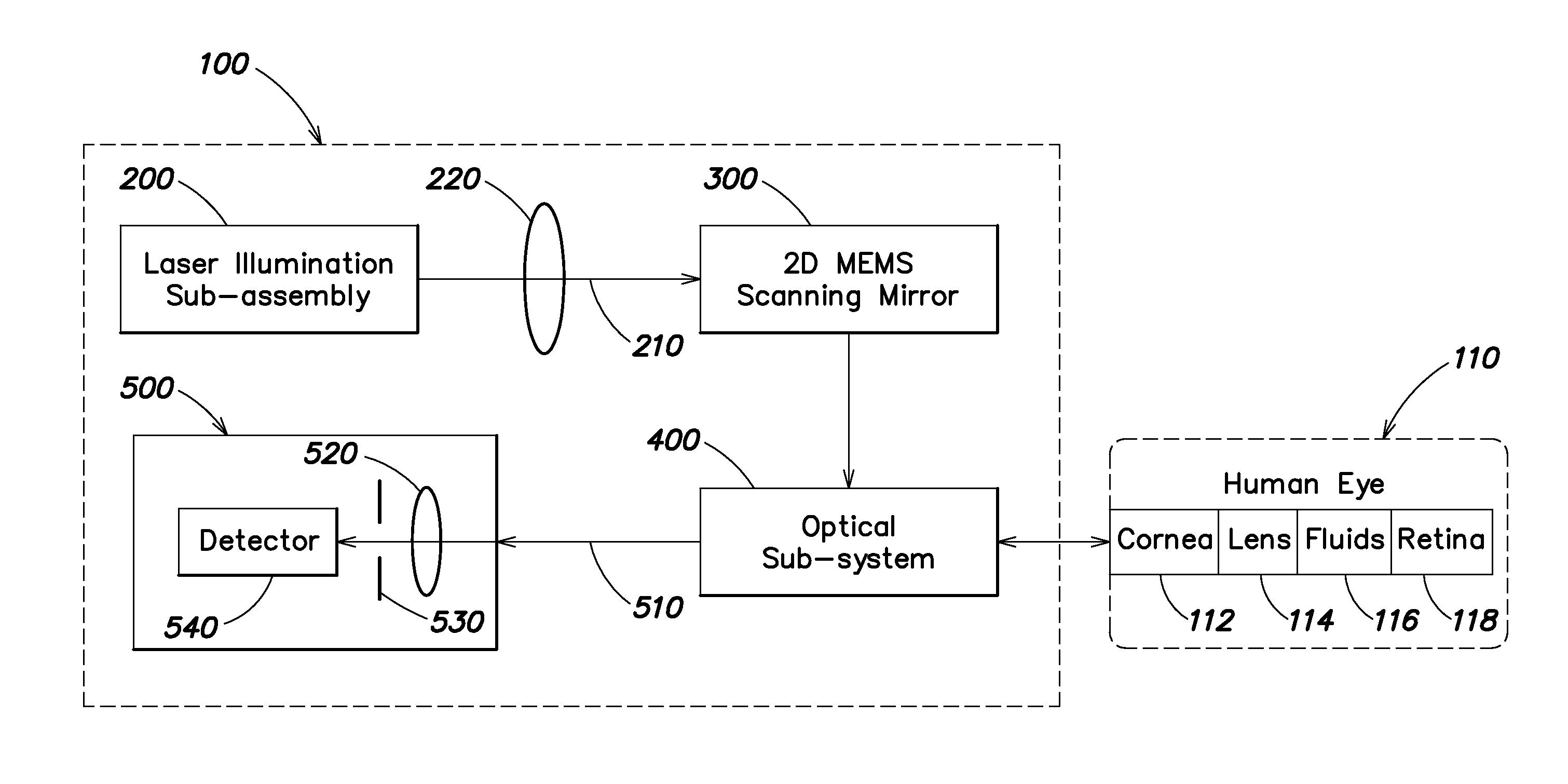
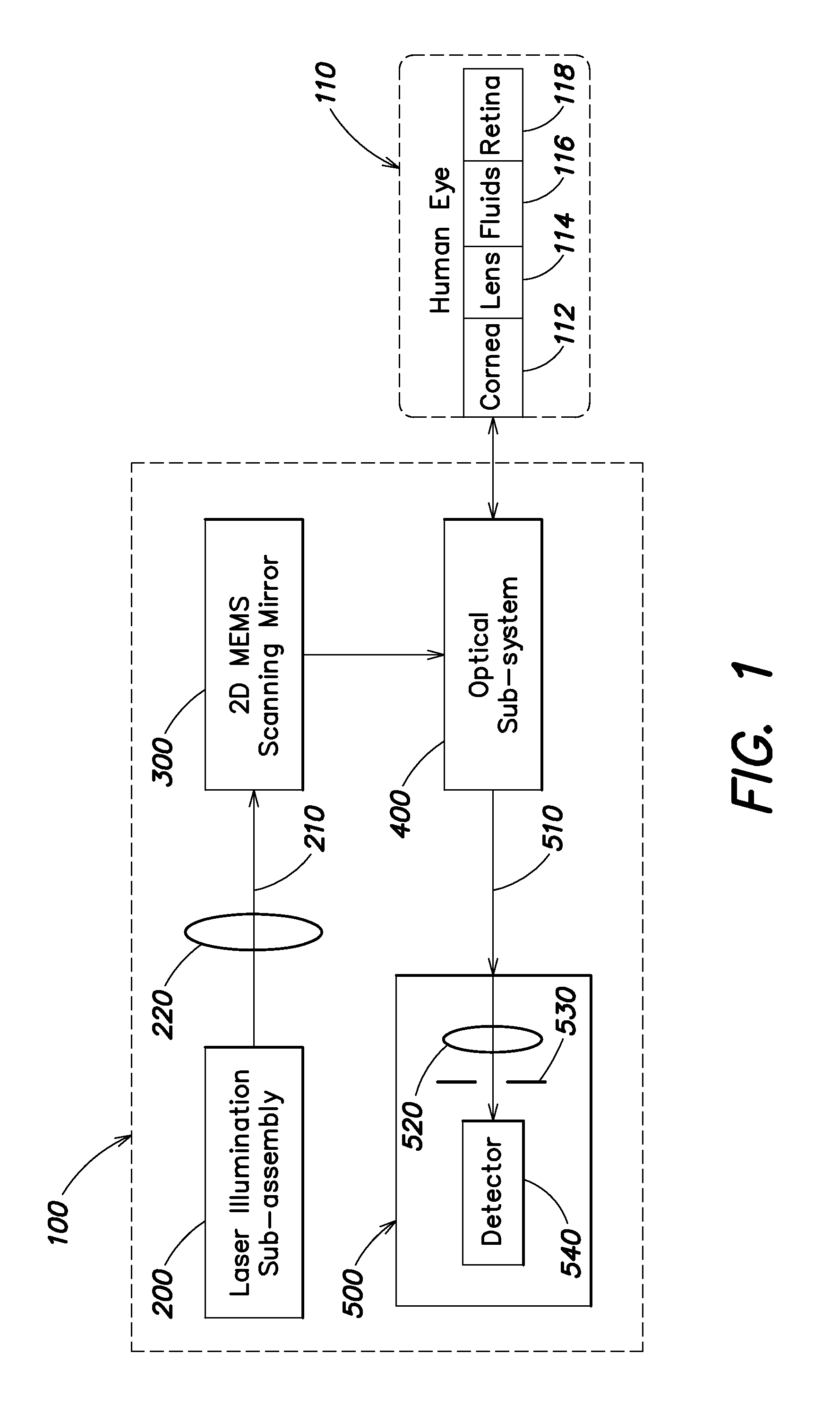
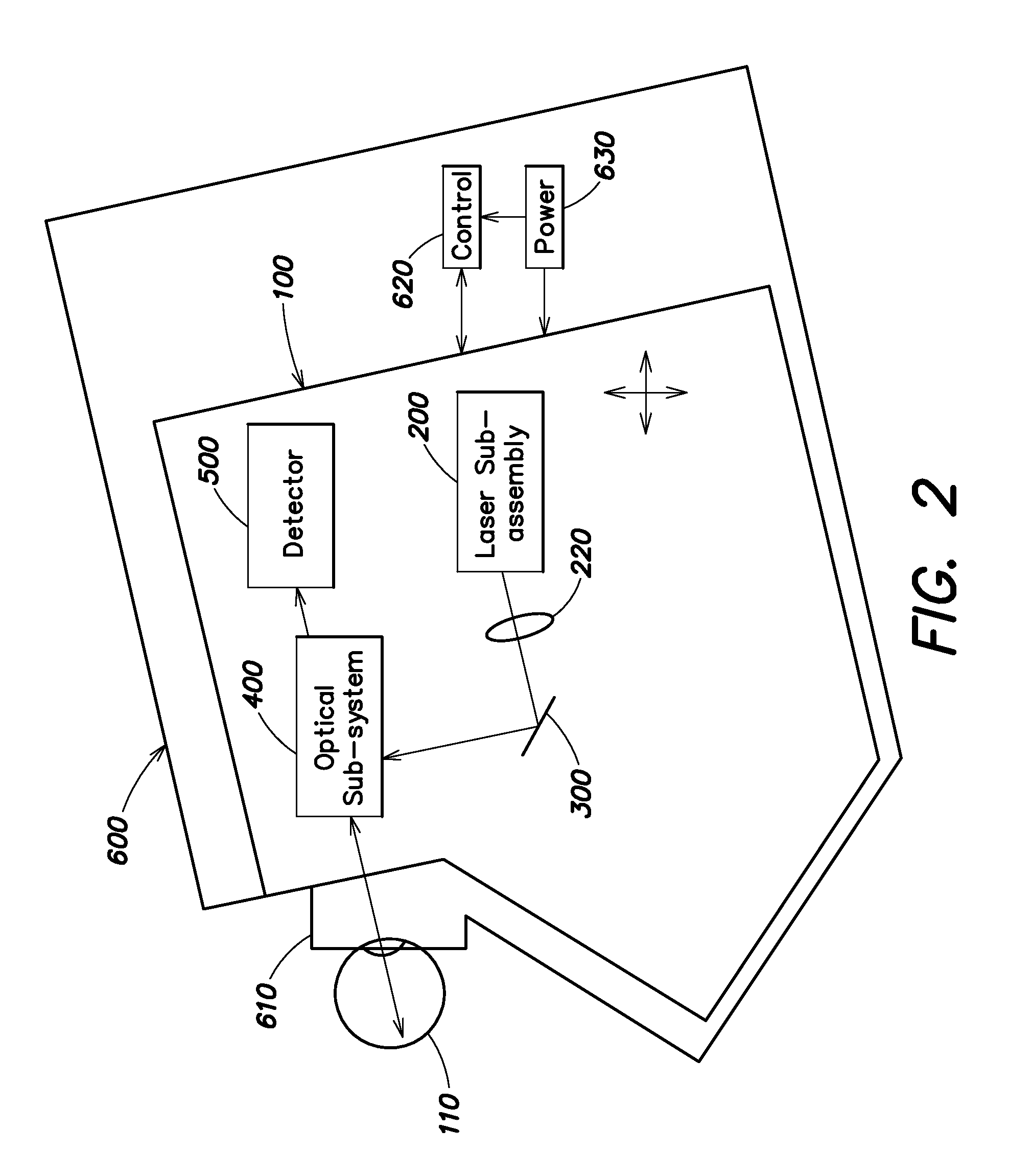
[0029]Aspects and embodiments are directed to a compact, wide-field scanning laser ophthalmoscope configured to enable handheld, portable retinal imaging, for example, in remote locations and primary-care-physician offices. Portable retinal imaging would be invaluable for screening remote populations for eye disease, and for screening warfighters for ocular injury in the battlefield, to monitor immediate ocular effects of battlefield trauma. Similarly, retinal imaging in a physician's office would greatly improve the efficiency of screening diabetics for retinopathy, for example. Conventional table-top retinal imaging devices are too large for such applications and / or require a trained expert to operate.

[0030]According to one embodiment, self-administered, wide-field imaging of the retina in a compact, portable hardware footprint is achieved with a MEMS-based scanning laser ophthalmoscope (MSLO). To enable robust scanning in a portable device, a two-dimensional (2D) MEMS scanning mi...


PUM


Abstract

A portable MEMS-based scanning laser ophthalmoscope (MSLO). In one example the MSLO includes a laser illumination sub-assembly that generates a laser illumination beam, a two-dimensional MEMS scan mirror configured to receive and scan the laser illumination beam over at least a portion of the retina of an eye to be imaged, an optical system configured to direct the laser illumination beam from the scan mirror into the eye to illuminate the retina, and a detector sub-assembly configured to intercept optical radiation reflected from the eye to generate an image of the retina. The optical system includes a polarized beamsplitter positioned between the scan minor and the eye and configured to direct the laser illumination beam to into the eye and to direct the optical radiation reflected from the eye to the detector sub-assembly.

Description

CROSS REFERENCE TO RELATED APPLICATIONS[0001]This application claims priority under 35 U.S.C. §120 to co-pending, commonly-owned U.S. application Ser. No. 13 / 440,464 titled “PORTABLE SELF-RETINAL IMAGING DEVICE” filed on Apr. 5, 2012, which claims priority under 35 U.S.C. §119(e) to U.S. Provisional Patent Application No. 61 / 472,986 titled “PORTABLE SELF-RETINAL IMAGING DEVICE” filed on Apr. 7, 2011 and to U.S. Provisional Patent Application No. 61 / 491,502 titled “PORTABLE SELF-RETINAL IMAGING DEVICE” filed on May 31, 2011, all of which are incorporated herein by reference in their entireties.BACKGROUND[0002]Ophthalmic fundus cameras have been used by ophthalmic specialists for many years to image the interior surface of the eye (the retina), including the fundus, optic disc, macula and fovea, and posterior pole. Generally, a fundus camera has approximately a 30 to 45 degree spherical field of view on the retina. These cameras operate on the principle of direct or indirect ophthalmo...

Claims


Application Information

Patent Timeline
Patent Type & Authority Applications(United States)
IPC IPC(8): A61B3/15A61B3/12A61B3/14
CPCA61B3/1025G02B21/0028G02B26/0833G02B26/101A61B3/14A61B3/12A61B3/15
Inventor FRANCIS, ROBERT PAULSUN, LAN
Owner RAYTHEON CO
Why Eureka
Try Eureka