
Illumination device, projecting device and lighting device

Active Publication Date: 2013-08-01
APPOTRONICS CORP LTD
View PDF7 Cites 50 Cited by
  • Summary
  • Abstract
  • Description
  • Claims
  • Application Information

AI Technical Summary

Benefits of technology

The present invention is an illumination device that uses a wavelength conversion material to produce a uniform mix of light. The device is designed to collect and use the excitation light efficiently, without adding scattering materials that could negatively impact its performance. This invention solves the problem of conflicting color uniformity and brightness in prior art illumination devices.

Problems solved by technology

The disadvantage of the device illustrated in FIG. 1a is that the output light contains the converted light only without the excitation light.
The device illustrated in FIG. 1b can obtain a mixed light composed of the excitation light and the converted light, but the mixed light often has problems in color uniformity.
But one problem of this solution is that the amount of the remaining excitation light is too small, which results in a low color temperature of the final output white light.
In other words, the requirement for a certain color temperature of the final output white light has confined the proportion of the excitation light and the converted light in the output light, so the usage of the phosphor materials has been limited.
However, a problem of adding scattering materials is that, as the scattering effect on the excitation light is increased, a certain portion of the excitation light will be reflected directly by the phosphor material layer and transmitted through the filter 115 as energy loss.
What is obvious is that, a better color uniformity of the required output light needs a larger amount of scattering materials added, which causes a greater loss of the excitation light and further a lower efficiency of the lighting device.

Method used


Image

  • Illumination device, projecting device and lighting device
  • Illumination device, projecting device and lighting device
  • Illumination device, projecting device and lighting device

Examples


first embodiment

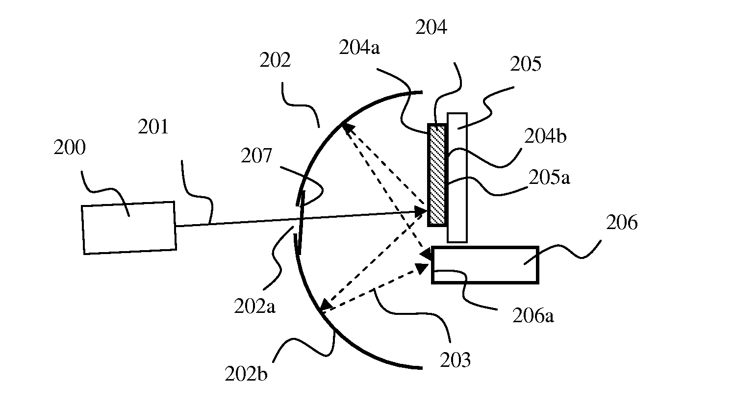
[0033]The illumination device according to the present invention, as shown in FIG. 2, includes an excitation light source 200 for generating an excitation light 201, and a wavelength conversion material layer 204 for absorbing a portion of the excitation light and emitting light having wavelength spectrum different from that of the excitation light. The wavelength conversion material layer 204 includes a first surface 204a which the excitation light 201 impinges on and a second surface 204b.

[0034]There are many choices for the excitation light source 200, such as LD (laser diode), LED (light emitting diode), or a mixture of the both, or other suitable light sources that can be used to excite wavelength conversion materials. The spectrum of the excitation light should include at least a part of spectrum of visible light if the illumination device of this embodiment is used for display or illumination or other applications for human eyes. Of the excitation light sources, blue LDs or ...

seventh embodiment

[0063]the present invention is illustrated in FIG. 8. The light guide device according to this embodiment includes an interference filter 802 for transmitting the excitation light 801 onto the first surface 804a of the wavelength conversion material layer 804. The filter 802 also acts as the substrate, similar to the substrate 405 in FIG. 4, to carry the wavelength conversion material 804. The spectral characteristic of the interference filter 802 is that it transmits the excitation light with incidence angles smaller than a first predefined angle and reflects the excitation light with incidence angles larger than a second predefined angle as well as the converted light.

[0064]The light traveling path during the working process of the illumination device according to this embodiment is shown in FIG. 8a. The excitation light 801 is transmitted through the interference filter 802 and incident on the wavelength conversion material layer 804. A first portion of the excitation light is ab...


PUM


Abstract

An illumination device includes a wavelength conversion material layer with a first surface, which includes a wavelength conversion material and a scattering material; a light guide device located adjacent the wavelength conversion material layer on a side facing its first surface for directing an excitation light onto the first surface of the wavelength conversion material layer, and for directing a mixed light emitted from the first surface, which includes converted light and remaining excitation light not absorbed by the wavelength conversion material layer, into a light exit port. In this illumination device, the light guide device can collect the excitation light reflected by the wavelength conversion material layer effectively, which insures that adding scattering materials into the wavelength conversion material layer doesn't have a significant impact on the luminous efficiency of the illumination device, and resolves the conflict between color uniformity and luminous efficiency of the device.

Description

BACKGROUND OF THE INVENTION[0001]1. Field of the Invention[0002]This invention relates to technical field of optical technology, and in particular, it relates to illumination devices, projecting devices and lighting devices.[0003]2. Description of the Related Art[0004]Currently, solid state light sources are widely used in general lighting, special lighting, projection and display due to their characteristics, such as long lifetime and environment friendly nature. Among these solid state light sources, the ones emitting white light show a great potential for development in the field of lighting.[0005]There are mainly two approaches to achieve solid state white light sources. One is that a plurality of different monochromatic light sources are packaged together to generate a mixed white light. For example, red (R), green (G), blue (B) LEDs (light emitting diodes) are turned on at the same time to obtain a white light. The other one is that yellow phosphor materials are stimulated by ...

Claims


Application Information

Patent Timeline
IPC IPC(8): G03B21/14F21V9/00F21V9/40
CPCF21V9/00G03B21/14G03B21/204G03B21/208F21Y2101/02F21Y2101/025F21V9/10F21V9/45F21Y2115/10F21Y2115/30
Inventor ZHANG, LILIXU, YANZHENG
Owner APPOTRONICS CORP LTD
Learn More