Photovoltaic Panel Circuitry

a photovoltaic panel and circuit technology, applied in the direction of mechanical actuation of burglar alarms, emergency protective arrangements for limiting excess voltage/current, and removal of hand-held portable objects, etc., can solve the performance of solar photovoltaic distributed power systems, power losses, and difficulty in verifying the correct operation of systems, so as to eliminate arcs

Active Publication Date: 2013-08-01
SOLAREDGE TECH LTD
View PDF2 Cites 86 Cited by
  • Summary
  • Abstract
  • Description
  • Claims
  • Application Information

AI Technical Summary

Benefits of technology

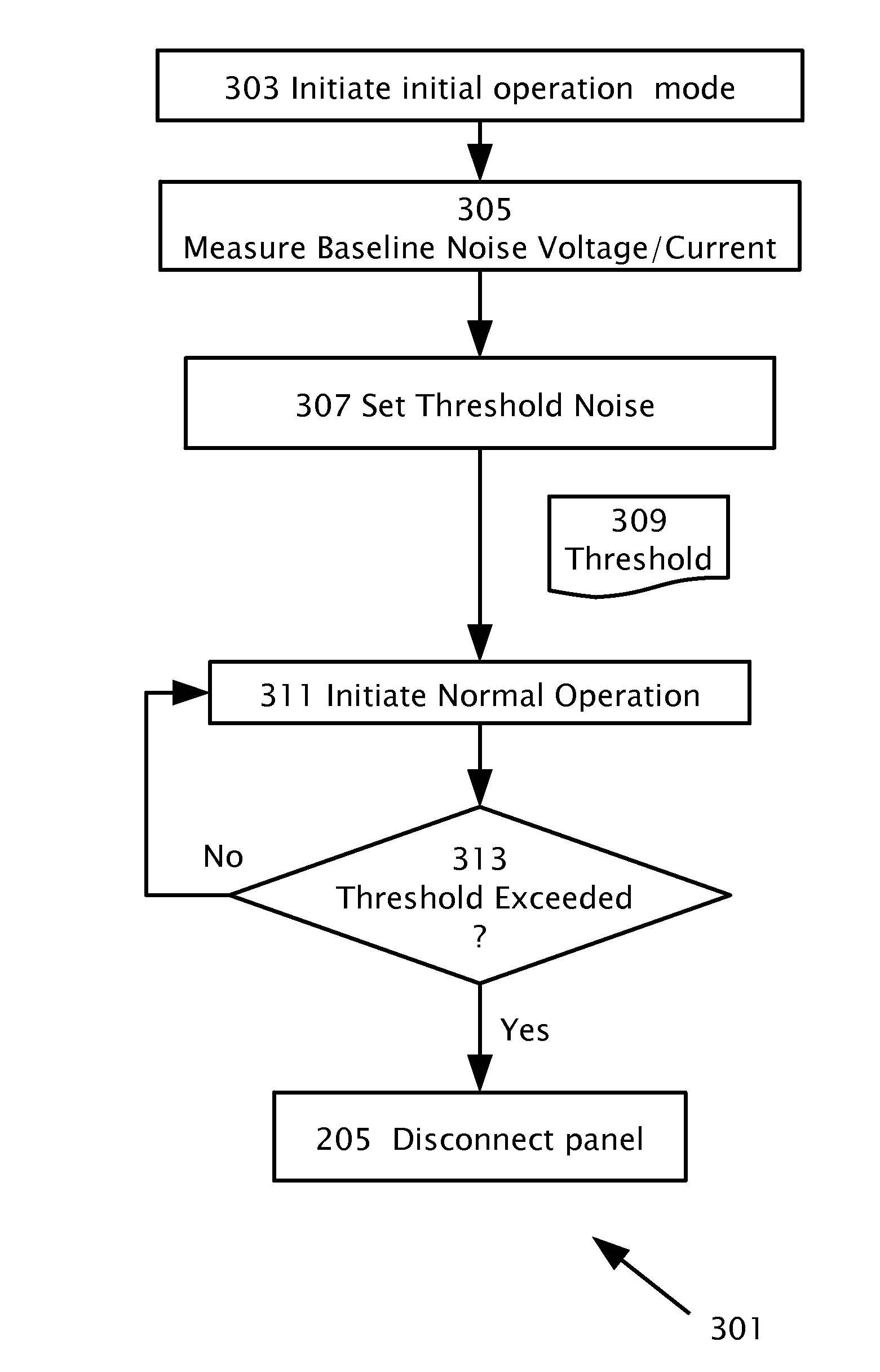
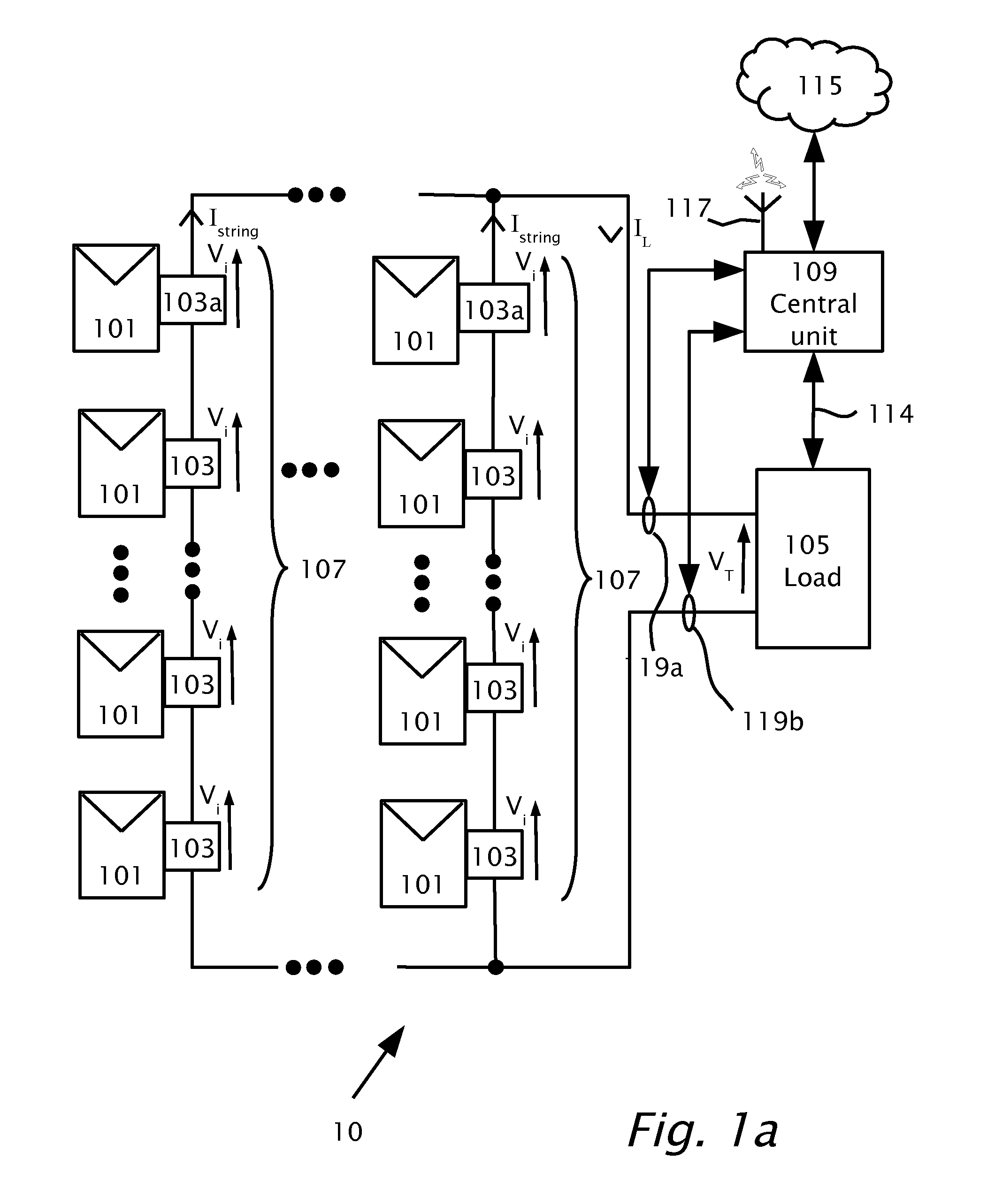
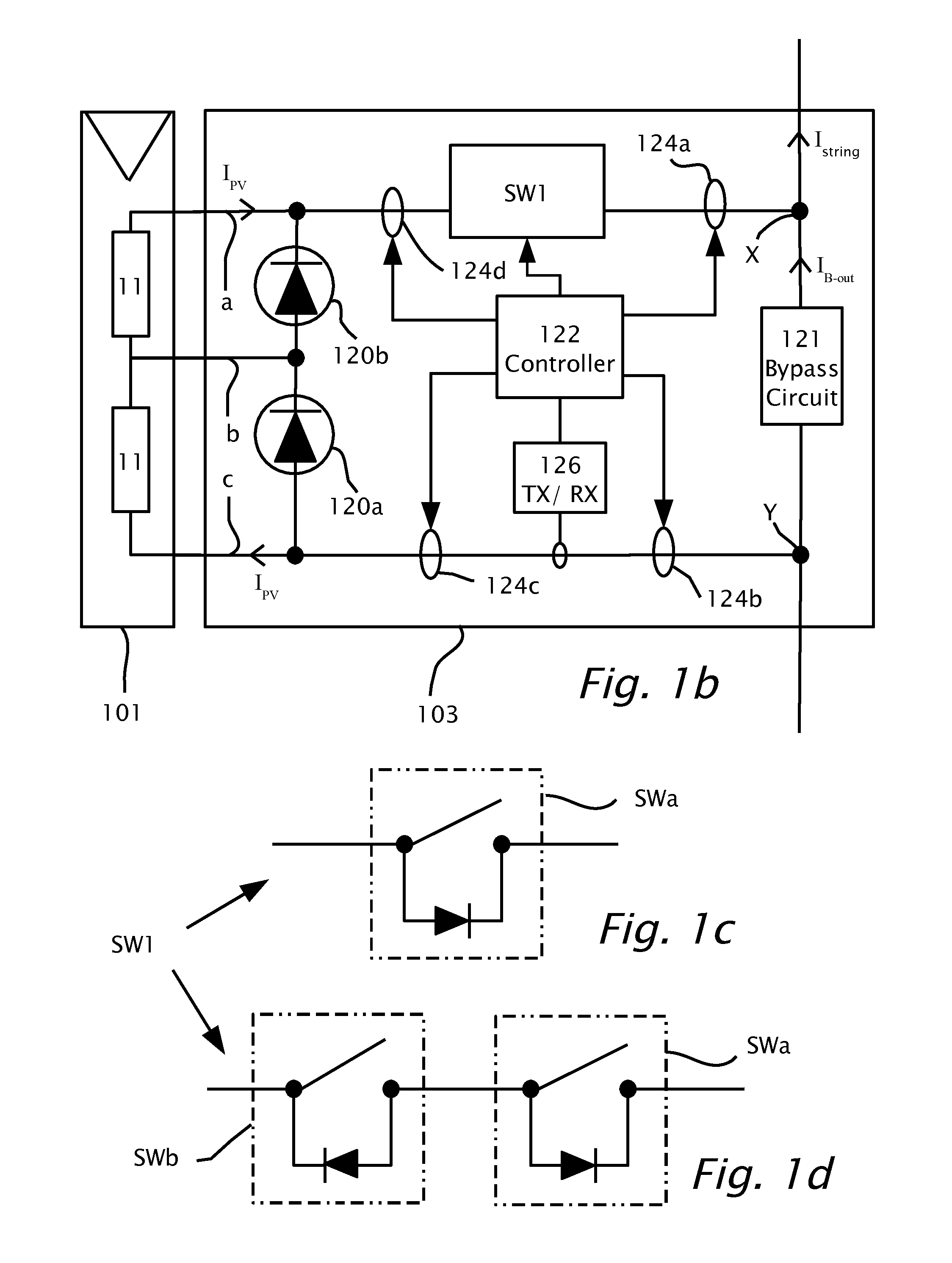
[0020]According to features of the present invention, there is provided a method performable in a photovoltaic solar power harvesting system. The method performs by a circuit integrated or integrable with a photovoltaic panel to form a photovoltaic module. The circuit has input terminals and output terminals. The circuit may include a controller adapted to monitor in parallel multiple types of malfunctions. The controller is adapted to control at least one switch connected between the input terminals and the output terminals to activate the switch and to disconnect thereby the photovoltaic panel from at least one of the output terminals and to bypass the output terminals upon detecting at least one of multiple malfunctions. The malfunctions monitored by the controller may include: an arc, a potential theft, a ground fault or a monitored parameter fault. The detection of the a

Problems solved by technology

Changes in temperature, solar irradiance and shading, either from near objects such as trees or far objects such as clouds, can cause power losses.
Owners and even professional installers may find it difficult to verify the correct operation of the system.
With time, many more factors, such as aging, dust and dirt collection and panel degradation affect the performance of the solar photovoltaic distributed power system .
Data collected at the inverter may not be sufficient to provide proper monitoring of the operation of the system.
However, a duplex transmission method requires additional transmission lines and complicates the system.
On the other hand, one-way transmission may be prone to collisions and makes it difficult to compare data transmitted from the various sources.
Due to the wide variability of power output of such systems, and the wide range of environmental conditions that affect the power output, the output parameters from the ov

Method used


Image

  • Photovoltaic Panel Circuitry
  • Photovoltaic Panel Circuitry
  • Photovoltaic Panel Circuitry

Examples


Embodiment Construction

[0031]Reference will now be made in detail to features of the present invention, examples of which are illustrated in the accompanying drawings, wherein like reference numerals refer to the like elements throughout. The features are described below to explain the present invention by referring to the figures.

[0032]Before explaining features of the invention in detail, it is to be understood that the invention is not limited in its application to the details of design and the arrangement of the components set forth in the following description or illustrated in the drawings. The invention is capable of other features or of being practiced or carried out in various ways. Also, it is to be understood that the phraseology and terminology employed herein is for the purpose of description and should not be regarded as limiting.

[0033]It should be noted, that although the discussion herein relates primarily to photovoltaic systems, the present invention may, by non-limiting example, alterna...


PUM


Abstract

Circuits integrated or integrable with a photovoltaic panel to provide built-in functionality to the photovoltaic panel including safety features such as arc detection and elimination, ground fault detection and elimination, reverse current protection, monitoring of the performance of the photovoltaic panel, transmission of the monitored parameters and theft prevention of the photovoltaic panel. The circuits may avoid power conversion, for instance DC/DC power conversion, may avoid performing maximum power tracking to include a minimum number of components and thereby increase overall reliability.

Description

BACKGROUND[0001]1. Technical Field[0002]Aspects of the present disclosure relate to distributed power systems, particularly a circuit for integrating with or attaching to a photovoltaic panel.[0003]2. Description of Related Art[0004]A conventional photovoltaic distributed power harvesting system multiple photovoltaic panels are interconnected and connected to an inverter. Various environmental and operational conditions impact the power output of the photovoltaic panels. For example, the solar energy incident, ambient temperature and other factors impact the power extracted from each photovoltaic panel. Dependent on the number and type of panels used, the extracted power may vary widely in the voltage and current from panel to panel. Changes in temperature, solar irradiance and shading, either from near objects such as trees or far objects such as clouds, can cause power losses. Owners and even professional installers may find it difficult to verify the correct operation of the syst...

Claims


Application Information

Patent Timeline
IPC IPC(8): H02H3/16
CPCH02H1/0015G08B13/14Y02E10/56H01L31/02021Y02E10/50H02H3/16H02S50/00H02H7/20H02S40/36
Inventor HAR-SHAI, LIRONZOHAR, ALONYOSCOVITCH, ILANGALIN, YOAVHANDELSMAN, LIOR
Owner SOLAREDGE TECH LTD
Why Eureka
Try Eureka