Interference Control Mechanism in Multi-Band Communication

a control mechanism and multi-band communication technology, applied in the field of multi-band communication interference control mechanisms, can solve the problems of insufficient rejection of current state-of-the-art filter technology, more complicated interference situations, and inability to solve interference problems by single generic rf design, etc., to achieve sufficient frequency separation, enhance data rates, and extend communication networks

Active Publication Date: 2013-08-01
AVAGO TECH INT SALES PTE LTD
View PDF20 Cites 57 Cited by
  • Summary
  • Abstract
  • Description
  • Claims
  • Application Information

AI Technical Summary

Benefits of technology

[0008]In the last years, an increasing extension of communication networks, e.g. of wire based communication networks, such as the Integrated Services Digital Network (ISDN), DSL, or wireless communication networks, such as the cdma2000 (code division multiple access) system, cellular 3rd generation (3G) communication networks like the Universal Mobile Telecommunications System (UMTS), enhanced communication networks based e.g. on LTE, cellular 2nd generation (2G) communication networks like the Global System for Mobile communications (GSM), the General Packet Radio System (GPRS), the Enhanced Data Rates for Global Evolutions (EDGE), or other wireless communication system, such as the Wireless Local Area Network (WLAN), Bluetooth or Worldwide Interoperability for Microwave Access (WiMAX), took place all over the world. Various organizations, such as the 3rd Generation Partnership Project (3GPP), Telecoms & Internet converged Services & Protocols for Advanced Networks (TISPAN), the International Telecommunication Union (ITU), 3rd Generation Partnership Project 2 (3GPP2), Internet Engineering Task Force (IETF), the IEEE (Institute of Electrical and Electronics Engineers), the WiMAX Forum and the like are working on standards for telecommunication network and access environments.
[0009]Generally, for properly establishing and handling a communication connection between communication elements such as a UE and another communication element or UE, a database, a server, etc., one or more intermediate network elements such as communication network control elements, support nodes or service nodes are involved which may belong to different communication networks.
[0010]In order to allow users to access various networks and services ubiquitously, an increasing number of UEs are equipped with multiple radio transceivers. For example, a UE may be equipped with LTE, WiFi, and Bluetooth transceivers, as well as GNSS receivers.
[0011]However, such a configuration may result in more complicated interference situations due to coexistence interference between those collocated radio transceivers. For example, due to extreme proximity of multiple radio transceivers within the same UE, the transmit power of one transmitter may be much higher than the received power level of another receiver.
[0012]Conventionally, it is tried by using filter technologies and sufficient frequency separation to avoid significant interference resulting from a transmit signal. However, for some coexistence scenarios, e.g. different radio technologies within the same UE operating on adjacent frequencies, current state-of-the-art filter technology might not provide sufficient rejection. Therefore, solving the interference problem by single generic RF design may not always be possible so that alternative methods have to be considered.
[0013]Examples of embodiments of the invention provide an apparatus, method and computer program product by means of which communications conducted in multiple different frequency bands can be controlled so as to decrease an interference level between the communications. In particular, examples of embodiments of the invention provide apparatuses, methods and computer program products providing interference control mechanisms by means of which communications conducted for example in an in-device co-existence scenario suffer less interferences from each other, in particular when using carrier aggregation.

Problems solved by technology

However, such a configuration may result in more complicated interference situations due to coexistence interference between those collocated radio transceivers.
However, for some coexistence scenarios, e.g. different radio technologies within the same UE operating on adjacent frequencies, current state-of-the-art filter technology might not provide sufficient rejection.
Therefore, solving the interference problem by single generic RF design may not always be possible so that alternative methods have to be considered.

Method used


Image

  • Interference Control Mechanism in Multi-Band Communication
  • Interference Control Mechanism in Multi-Band Communication
  • Interference Control Mechanism in Multi-Band Communication

Examples


Embodiment Construction

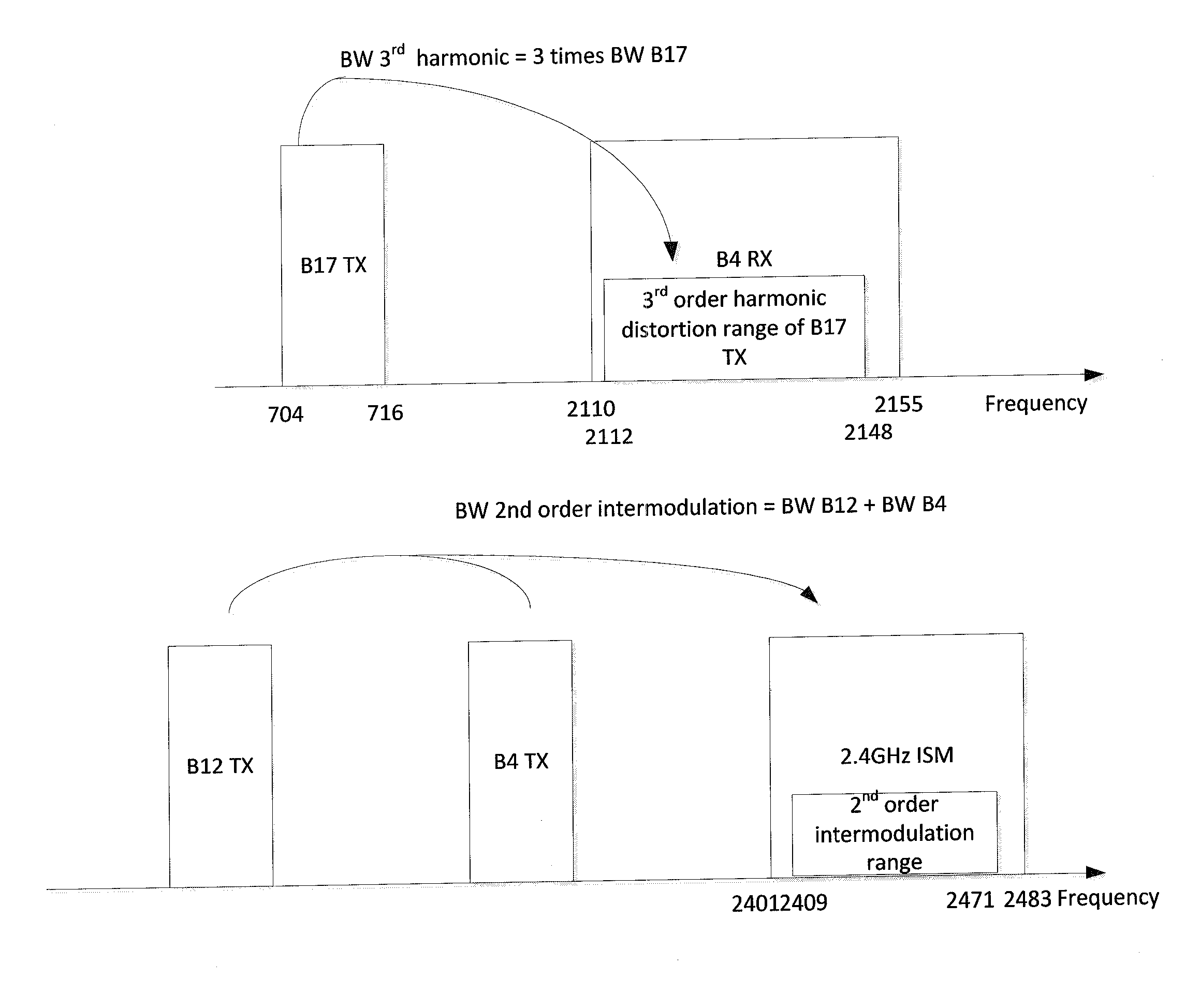
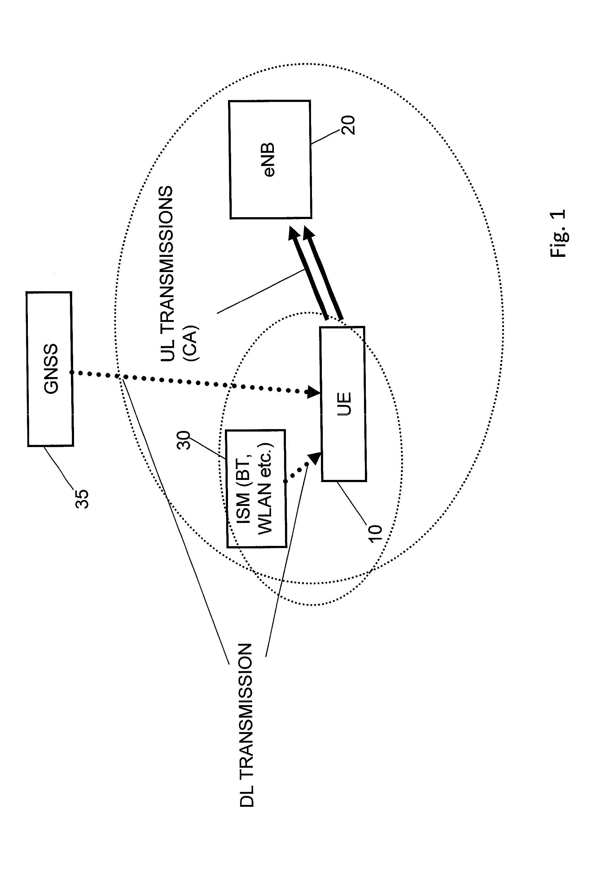
[0035]In the following, examples and embodiments of the present invention are described with reference to the drawings. For illustrating the present invention, the examples and embodiments will be described in connection with a cellular communication network based on a 3GPP LTE or LTE-A system wherein at least one further communication network is provided with which a UE can conduct a communication, such as an ISM network or a GSNN system. However, it is to be noted that the present invention is not limited to an application using such types of communication systems, but is also applicable in other types of communication systems and the like as long as interferences between communications may occur.

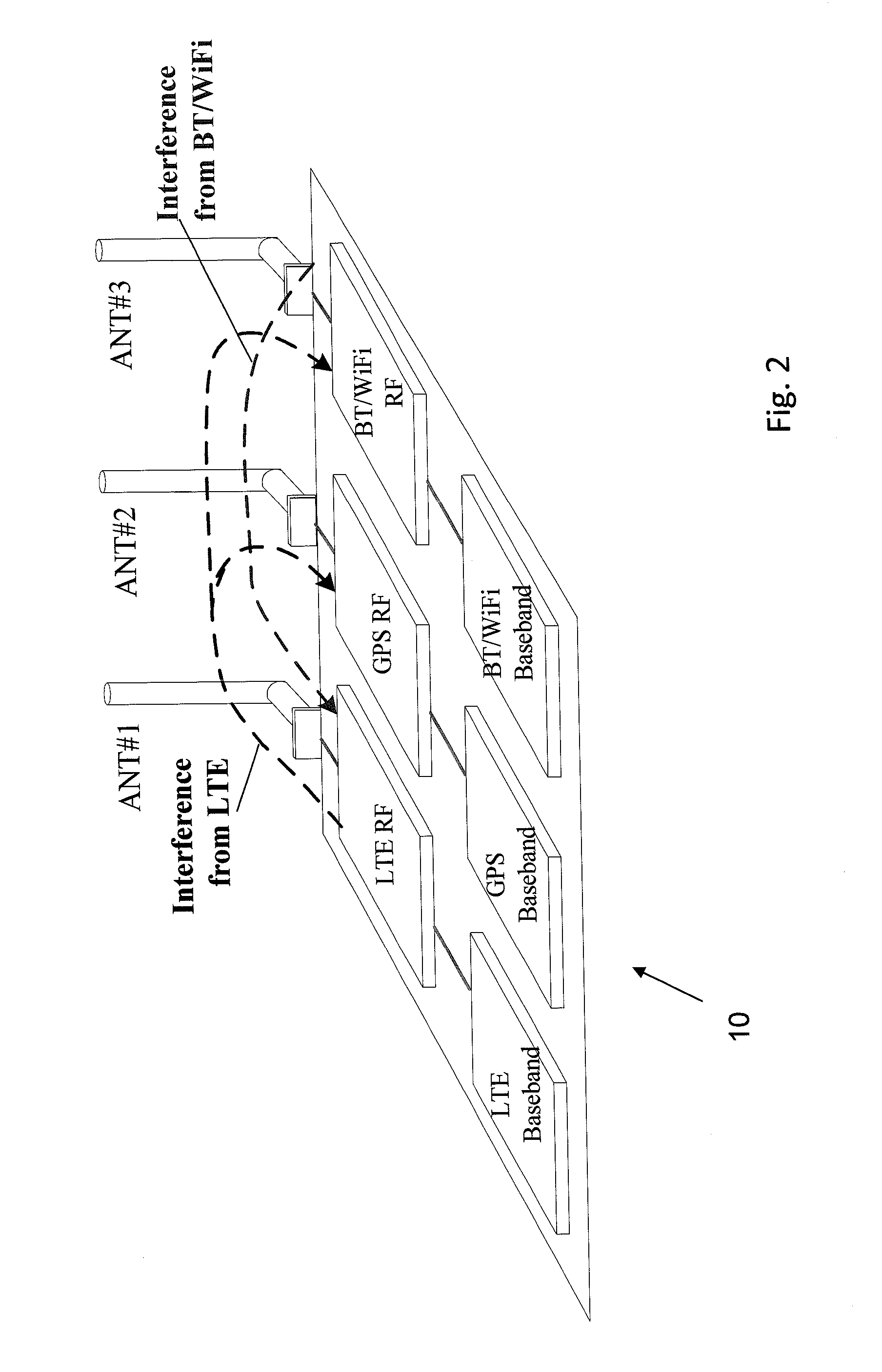
[0036]A basic system architecture of a communication network where examples of embodiments of the invention are applicable may comprise a commonly known architecture of one or more communication systems comprising a wired or wireless access network subsystem and a core network. Such an ar...


PUM


Abstract

There is provided a mechanism for controlling communications conducted in multiple frequency bands so as to decrease an interference level between the communications. When an interference situation caused between a first set UL communications performed on at least two different frequency bands and a DL communication performed on another frequency band is determined, a frequency carrier deactivation processing is conducted so as to deactivate either one of carriers of the at least two frequency bands of the set of UL communications. The deactivation processing comprises for example an autonomous denial on the UE side or an interference reporting with deactivation on the eNB side.

Description

BACKGROUND OF THE INVENTION[0001]1. Field of the Invention[0002]The present invention relates to a mechanism for controlling communications conducted in multiple frequency bands so as to decrease an interference level between the communications. In particular, the present invention is directed to apparatuses, methods and computer program products providing interference control mechanisms by means of which communications conducted for example in an in-device co-existence scenario suffer less interferences from each other, in particular when using carrier aggregation.[0003]2. Related Background Art[0004]Prior art which is related to this technical field can e.g. be found in technical specifications according to 3GPP TR 36.816 (e.g. version 11.2.0).[0005]The following meanings for the abbreviations used in this specification apply:BS: base stationBT: Bluetooth[0006]CA: carrier aggregationCC: component carrierCPU: central processing unitCSI: channel state informationDL: downlinkDRX: dis...

Claims


Application Information

Patent Timeline
Patent Type & Authority Applications(United States)
IPC IPC(8): H04W24/00H04W72/04H04W76/34
CPCH04B1/525H04W16/14H04W88/06H04W72/1215H04W76/064H04W72/082H04W76/34H04W72/541
Inventor IMMONEN, ANTTI OSKARIKAUKOVUORI, JOUNI KRISTIANISOKANGAS, JARIRANTA, JUKKA
Owner AVAGO TECH INT SALES PTE LTD
Why Eureka
Try Eureka