Method and apparatus for scheduling communication for low capability devices

a technology of low capability and communication channel, applied in the field of wireless communication systems, can solve the problems of extension of dl control region, limited capacity of control region, and inability to achieve interference coordination in frequency domain, and achieve the effect of reducing pdcch overhead

Active Publication Date: 2013-08-01
SAMSUNG ELECTRONICS CO LTD
View PDF6 Cites 203 Cited by
  • Summary
  • Abstract
  • Description
  • Claims
  • Application Information

AI Technical Summary

Benefits of technology

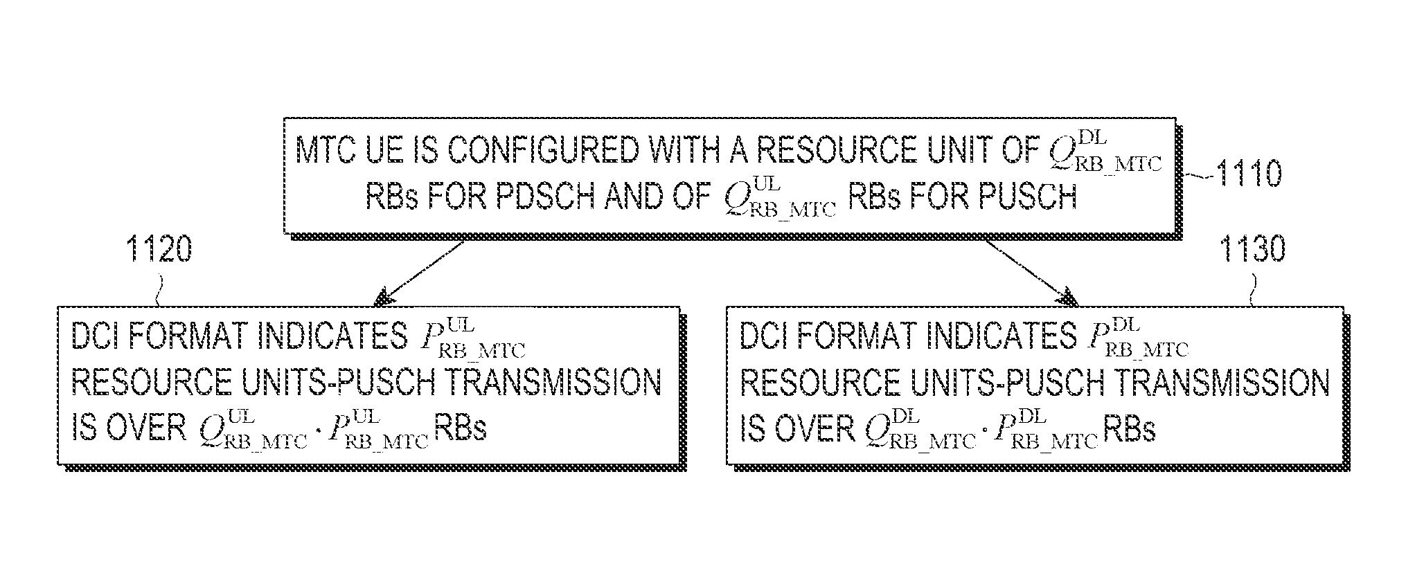
[0069]Aspects of the present invention are to address at least the above-mentioned problems and or disadvantages and to provide at least the advantages described below. Accordingly, an aspect of the present invention is to provide methods and apparatuses to design transmissions modes and respective DL Control Information (DCI) formats associated with PDSCH transmissions to MTC UEs or PUSCH transmissions from MTC UEs, reduce a PDCCH overhead associated with scheduling PDSCH transmissions to MTC UEs or PUSCH transmissions from MTC UEs, and to define different coding methods for data transmitted to an MTC UE than for data transmitted from an MTC UE.

Problems solved by technology

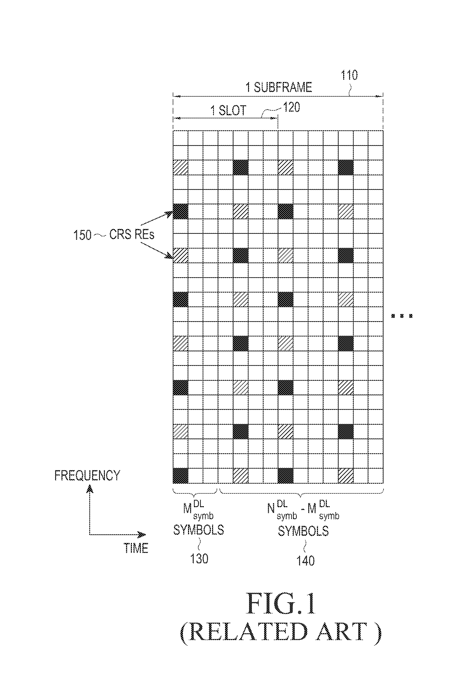
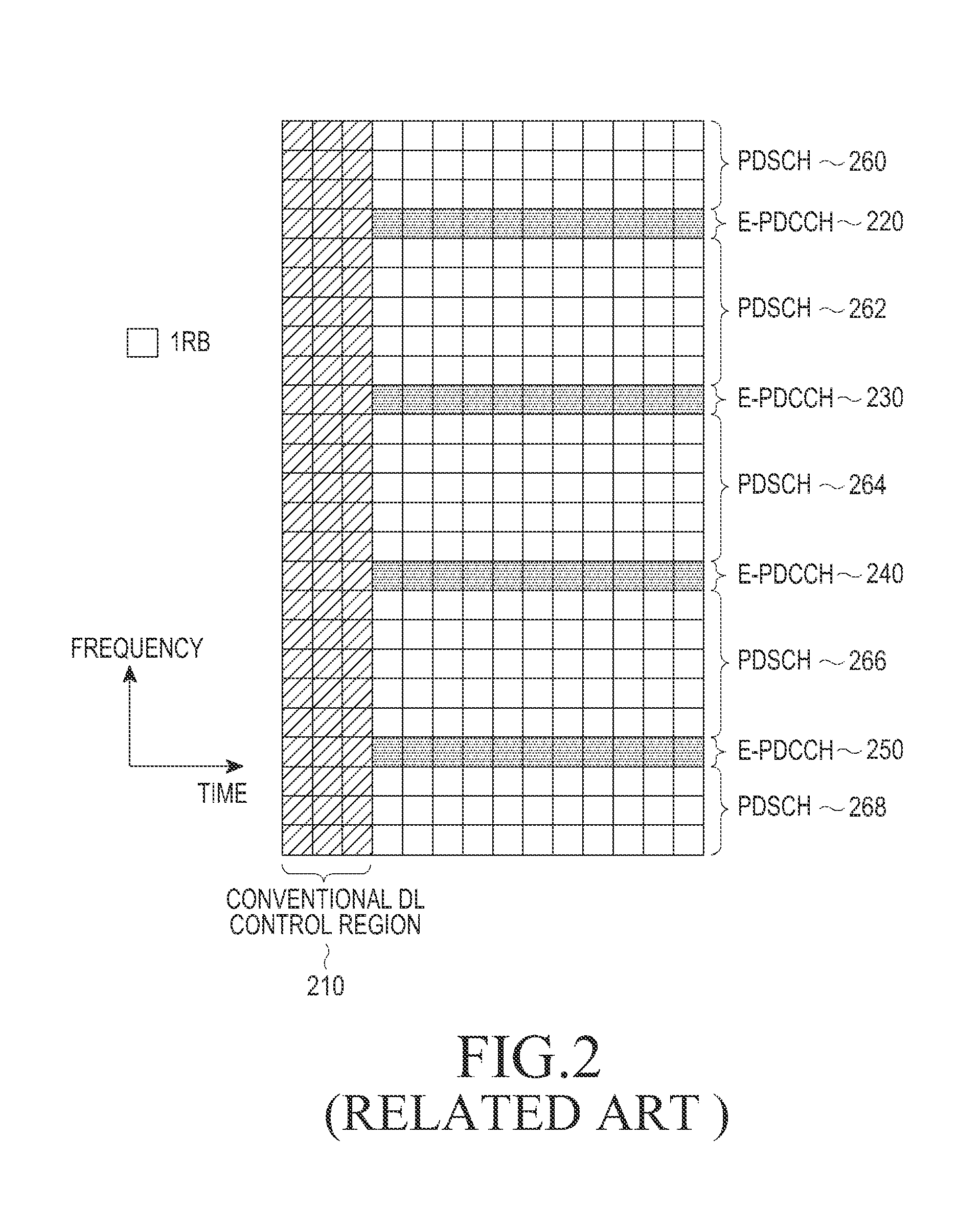
As a consequence, such control region has limited capacity and cannot achieve interference coordination in the frequency domain.
A direct extension of a DL control region as in FIG. 1 to more than MsymbDL=3 subframe symbols is not possible at least due to a requirement to support UEs which cannot be aware of such extension.
RF costs are related to implementation and production methods as well as to design choices.
DBB costs are related to the communication capabilities of MTC UEs and are dominated by the receiver complexity which is typically about an order of magnitude larger than the transmitter complexity.
A complexity of a PDCCH decoder depends on a number of decoding operations an MTC UE performs per subframe.

Method used


Image

  • Method and apparatus for scheduling communication for low capability devices
  • Method and apparatus for scheduling communication for low capability devices
  • Method and apparatus for scheduling communication for low capability devices

Examples


Embodiment Construction

[0101]The following description with reference to the accompanying drawings is provided to assist in a comprehensive understanding of exemplary embodiments of the invention as defined by the claims and their equivalents. It includes various specific details to assist in that understanding but these are to be regarded as merely exemplary. Accordingly, those of ordinary skill in the art will recognize that various changes and modifications of the embodiments described herein can be made without departing from the scope and spirit of the invention. In addition, descriptions of well-known functions and constructions may be omitted for clarity and conciseness.

[0102]The terms and words used in the following description and claims are not limited to the bibliographical meanings, but, are merely used by the inventor to enable a clear and consistent understanding of the invention. Accordingly, it should be apparent to those skilled in the art that the following description of exemplary embod...


PUM


Abstract

Methods and apparatus are described for a User Equipment (UE) with reduced processing capabilities (e.g., Machine Type Communication (MTC) UE) to transmit and receive signaling are provided. The Downlink Control Information (DCI) formats scheduling a transmission of a Physical Uplink Shared CHannel (PUSCH) or a reception of a Physical Downlink Shared CHannel (PDSCH) are designed and have a smaller size than respective DCI formats for conventional UEs. DCI formats scheduling PUSCHs to or PDSCHs for a group of MTC UEs are also designed and can have a same size as DCI formats scheduling PUSCH or PDSCH for an individual MTC UE.

Description

PRIORITY[0001]This application claims the benefit under 35 U.S.C. §119(e) to a United States Provisional application filed on Jan. 26, 2012 in the U.S. Patent and Trademark Office and assigned Ser. No. 61 / 590,991, the entire disclosure of which are incorporated herein by reference.BACKGROUND OF THE INVENTION[0002]1. Field of the Invention[0003]The present invention relates to wireless communication systems. More particularly, the present invention relates to the design of downlink control information formats scheduling data transmissions to or data receptions from User Equipment (UE) with limited capabilities.[0004]2. Description of the Art[0005]A communication system includes a DownLink (DL) that conveys transmission signals from transmission points such as Base Stations (BS or NodeBs) to User Equipments (UEs), and an UpLink (UL) that conveys transmission signals from UEs to reception points such as NodeBs. A UE, also commonly referred to as a terminal or a mobile station, may be f...

Claims


Application Information

Patent Timeline
Patent Type & Authority Applications(United States)
IPC IPC(8): H04W72/04
CPCH04W72/042H04L1/0036H04L1/0061H04L5/00H04L1/0071H04L1/1819H04L1/1822H04L1/0067H04L1/0038H04L1/1671H04L5/0053H04L1/18H04W72/23
Inventor PAPASAKELLARIOU, ARISJI, HYOUNG-JUKIM, YOUNG-BUM
Owner SAMSUNG ELECTRONICS CO LTD
Why Eureka
Try Eureka