Automatic positioning of imaging plane in ultrasonic imaging

a positioning device and ultrasonic imaging technology, applied in the field of ultrasonic imaging, can solve problems such as inflexible system us

Active Publication Date: 2013-08-01
KONINKLIJKE PHILIPS ELECTRONICS NV
View PDF19 Cites 22 Cited by
  • Summary
  • Abstract
  • Description
  • Claims
  • Application Information

AI Technical Summary

Benefits of technology

[0009]In this respect, the inventors of this invention realized that, with prior art methods and systems the user does not get a good overview of which obstacles the interventional object may encounter along its trajectory. Thus, a “virtual endoscope” is provided with an ultrasonic imaging device. Preferably, this method involves adjusting a C-plane (when MPR is used) or a transverse plane (when using bi-plane ultrasound) so that it is always slightly forward of the needle tip. When using MPR, the needle shaft is preferably always normal to the C-plane. This imaging plane configuration notably provides the user with information on immediate landscape forward of the needle tip, allowing the user to anticipate and adjust the needle trajectory if needed, in order to avoid for example the hitting of a major vessel.

Problems solved by technology

However, this system is not very flexible in use such that there is a need for alternative imaging methods and systems.

Method used


Image

  • Automatic positioning of imaging plane in ultrasonic imaging
  • Automatic positioning of imaging plane in ultrasonic imaging
  • Automatic positioning of imaging plane in ultrasonic imaging

Examples


Embodiment Construction

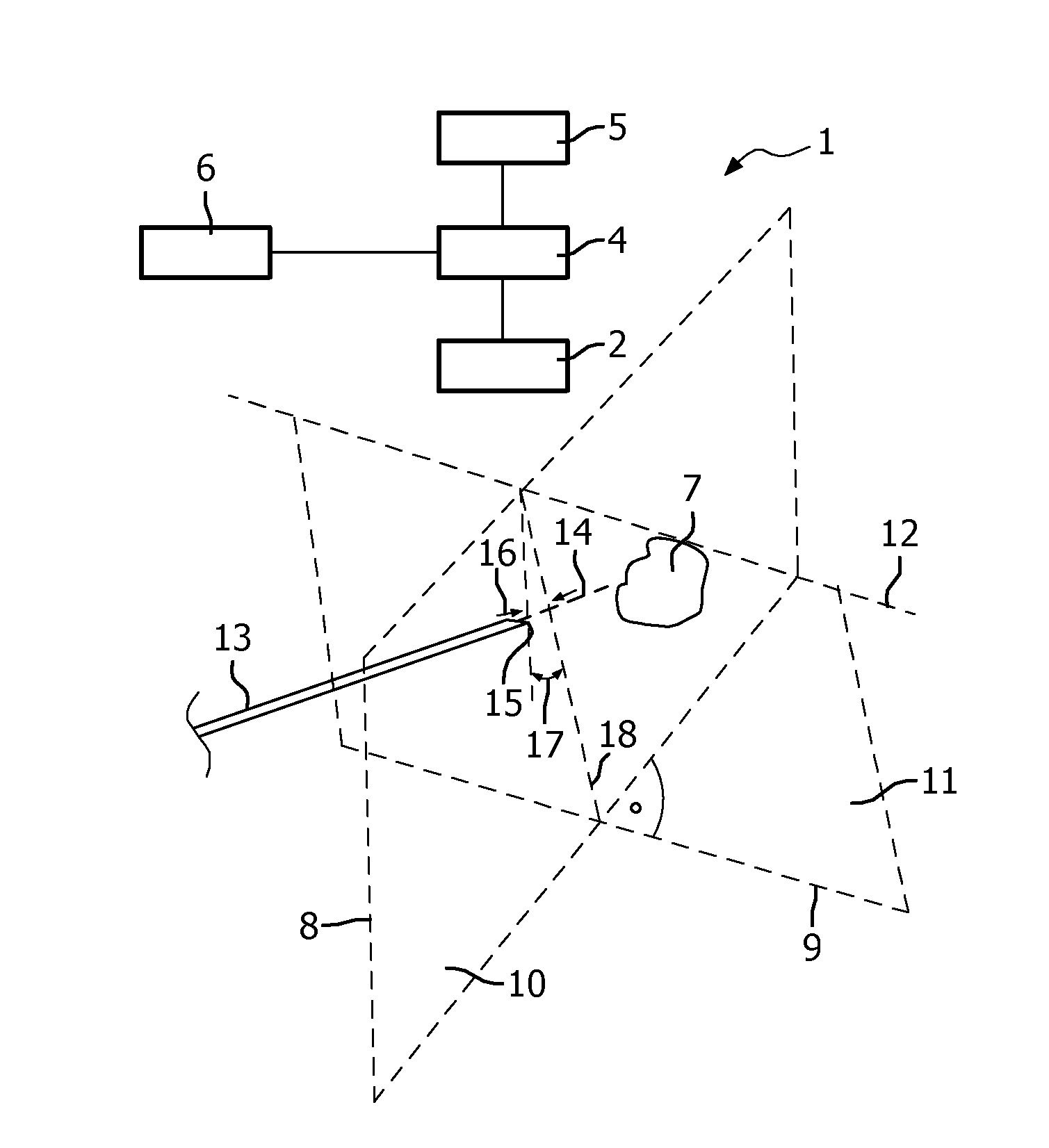
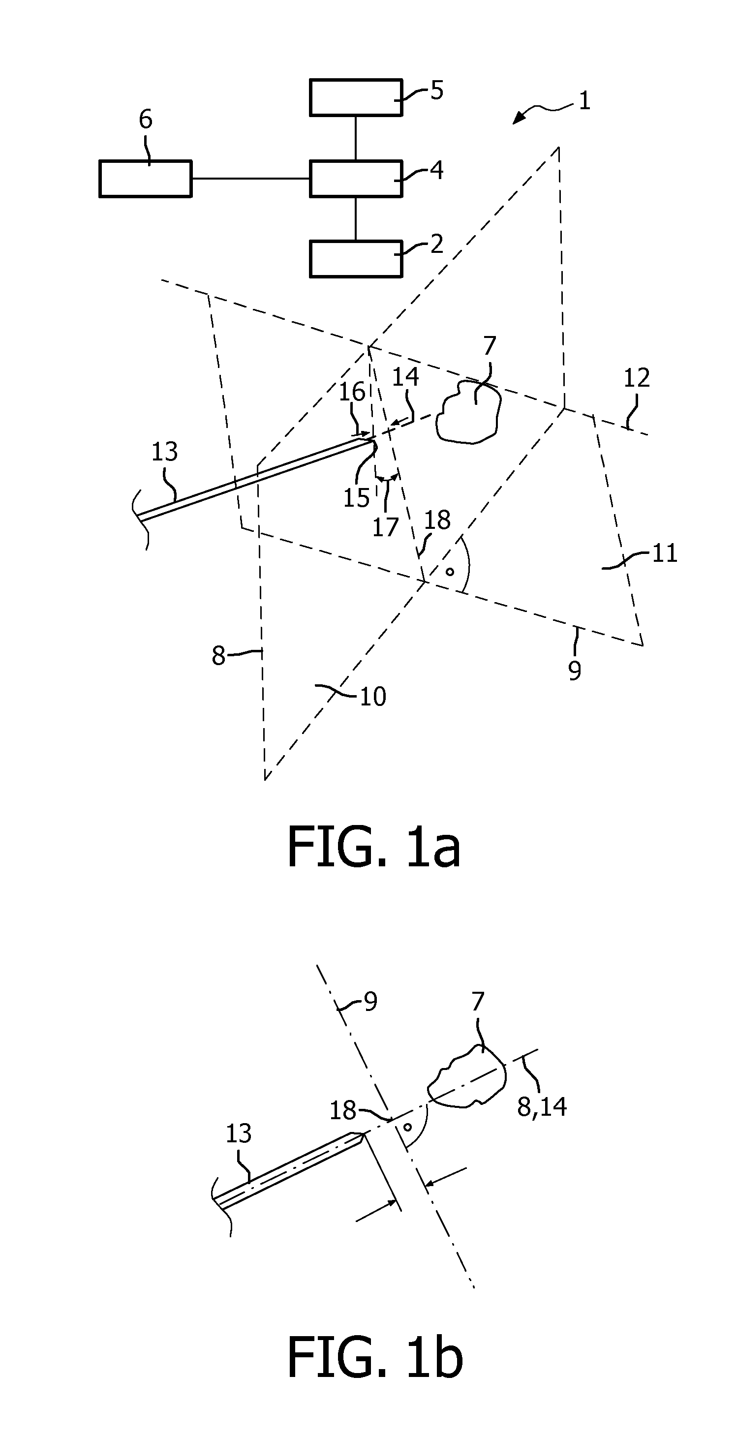
[0019]FIG. 1a schematically shows an imaging system 1 according an embodiment of the invention. FIG. 1a further illustrates two imaging planes in a three-dimensional view and FIG. 1b shows a top view projection, as seen from the transducer active aperture, of these imaging planes along a plane containing the longitudinal axis of the needle. FIGS. 1a and 1b exemplary show the case of bi-plane ultrasound imaging, however, the teaching of this invention is equally applicable in Multi-Planar Reconstruction (MPR). In MPR and in bi-plane ultrasound imaging, it is possible to display simultaneously at least two perpendicular imaging planes, one of which lying along the main axis of an interventional device, such as a medical needle, the other of which lying, in the top view of FIG. 1b, perpendicularly to the main axis of the interventional device. Such a configuration is useful when guiding an interventional device to a target lesion under real-time ultrasound guidance.

[0020]FIG. 1a shows ...


PUM


Abstract

The invention is directed to a method for ultrasonic imaging, in which two-dimensional images (10, 11) are acquired, one of which is aligned with a longitudinal direction of an interventional object (e.g. a needle) (13) to be moved towards a target area (7) within a subject of examination and the other one is intersecting the longitudinal direction of the interventional object (13) and automatically positioned dependent on the automatically determined position and orientation of the interventional object (13). Further, the invention is directed to an ultrasonic imaging device (1) adapted to conduct such a method.

Description

FIELD OF THE INVENTION[0001]The invention relates to a method for ultrasonic imaging using at least two two-dimensional images intersecting each other, an ultrasonic imaging device adapted to conduct such a method, a system containing such an ultrasonic imaging device, a computer program for executing such a method and a computer readable medium for storing such a computer program.BACKGROUND OF THE INVENTION[0002]Real-time ultrasound is routinely used to guide interventional procedures, such as biopsies and local ablative therapies (incl. radio-frequency ablation). With the recent introduction of real-time Multi-Planar Reconstruction (MPR) and bi-plane ultrasound on mechanical and matrix transducers it is now possible to gather in real-time anatomical information in any arbitrary planes. In bi-plane ultrasound imaging, two imaging planes are generated both of which intersect the transducer active aperture. MPR is a method for reconstructing two-dimensional images from a set of raw i...

Claims


Application Information

Patent Timeline
Patent Type & Authority Applications(United States)
IPC IPC(8): G06T7/00H04N5/30
CPCA61B5/06A61B8/0833A61B8/0841A61B8/14H04N5/30A61B8/463A61B8/523G06T7/0042A61B8/4245G06T7/73A61B5/062
Inventor GAUTHIER, THOMAS PATRICE JEAN ARSENEJAGO, JAMES ROBERTSON
Owner KONINKLIJKE PHILIPS ELECTRONICS NV
Why Eureka
Try Eureka