Compressor

a compression device and compressor technology, applied in the field of compression devices, can solve the problems of possible damage to the sealing surface, unstable dynamic pressure, etc., and achieve the effect of suppressing the liquefaction of the supplied sealing gas

Active Publication Date: 2013-08-01
KOBE STEEL LTD
View PDF11 Cites 11 Cited by
  • Summary
  • Abstract
  • Description
  • Claims
  • Application Information

AI Technical Summary

Benefits of technology

[0017]According to the present invention, even when the liquid such as drain and the like infiltrates to the sealing gas, or even when liquefaction of the sealing gas of the supplied liquid occurs, the liquid can be quickly discharged toward the intake channel along with the sealing gas through the dra...

Problems solved by technology

Also, when liquid (drain and the like) infiltrates to the seal surface formed by the dry gas seal, dynamic pressure formed becomes unstable, and the gap is not formed stably between the rotating ring and the stationary rings...

Method used


Image

  • Compressor
  • Compressor
  • Compressor

Examples


first embodiment

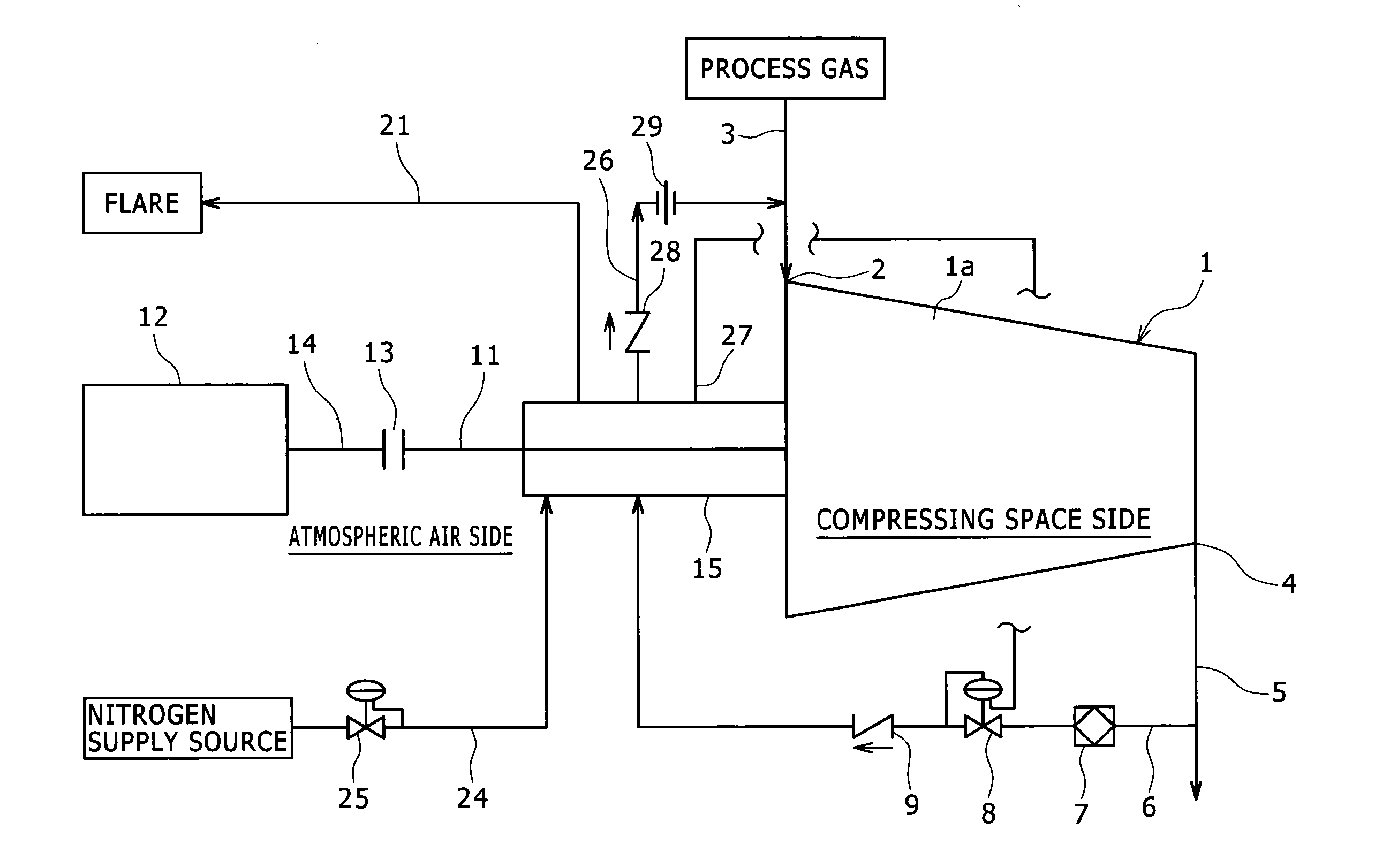
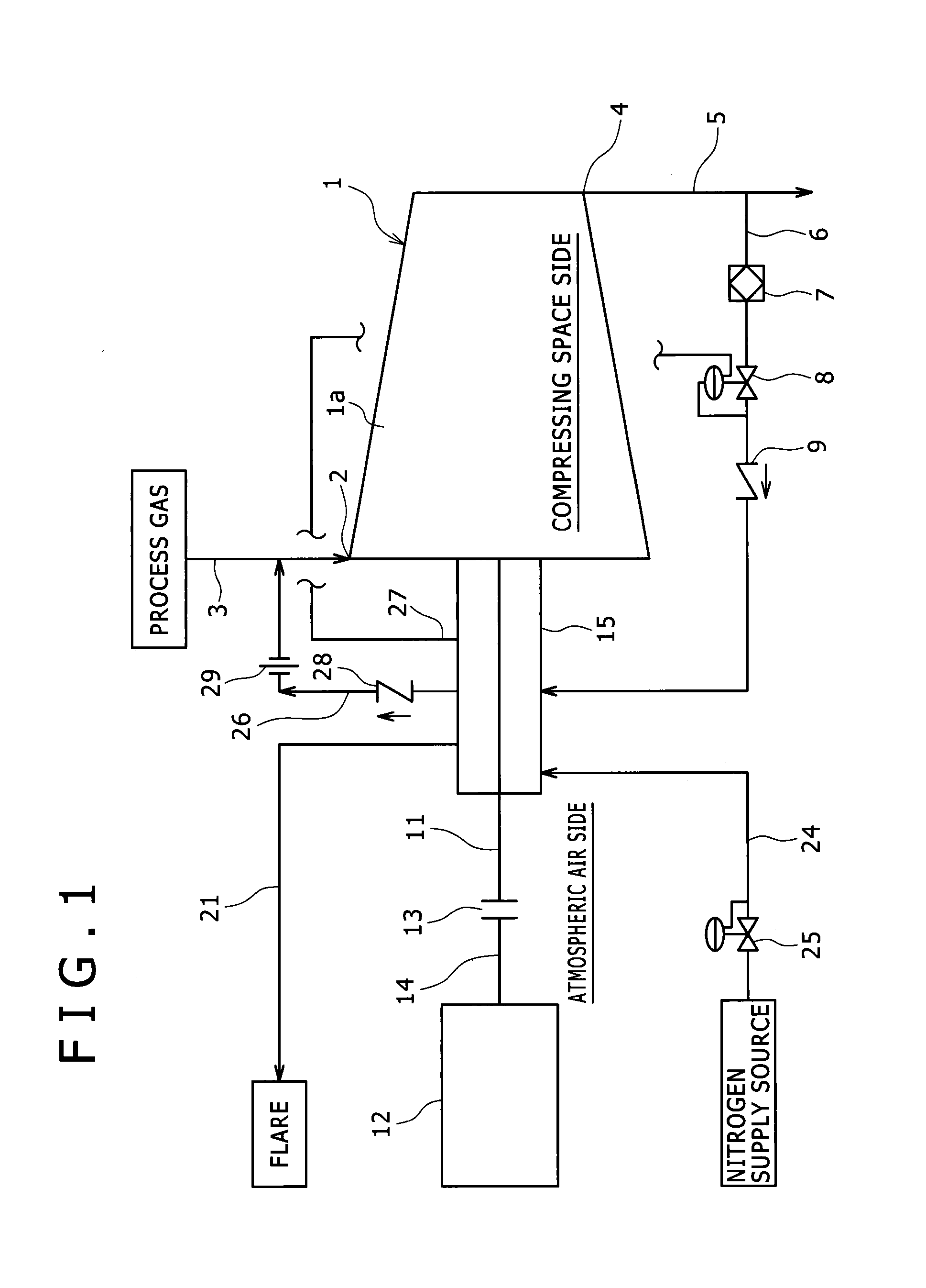
[0027]FIG. 1 shows a compressor of the present invention. The compressor in relation with the present invention includes a compressor body 1 in which a rotating body (rotor) (not illustrated) is accommodated in a compressing space (not illustrated) formed in a casing 1a.

[0028]An intake channel 3 is connected to an intake port 2 of the compressor body 1. Also, a discharge channel 5 is connected to a discharge port 4 of the compressor body 1.

[0029]The compressor body 1 sucks liquid to be compressed for example so-called process gas from the intake port 2 through the intake channel 3. Also, the compressor body 1 compresses the process gas in the compressing space described above, thereafter discharges it from the discharge port 4, and supplies it to a destination to be supplied not illustrated through the discharge channel 5.

[0030]Further, a sealing gas channel 6 with one end connected to the discharge channel 5 and the other end connected to a dry gas seal 15 described below is provi...

second embodiment

[0056]As shown in FIG. 8, instead of providing the emergency channel 31 in the compressor of the second embodiment, a sealing gas supply source 45 supplying nitrogen as the sealing gas may be connected to the sealing gas channel 6 via a check valve 44. According to this constitution, the sealing gas can be surely supplied from the sealing gas supply source 45 to the sealing gas channel 6. Accordingly, a constitution of saving the emergency channel 31 can be achieved. Further, it is also possible to provide both of the sealing gas supply source 45 and the emergency channel 31. In this case, the sealing gas can be surely supplied from the sealing gas channel 6 to the casing 1a.

[0057]Instead of connecting the pressure reference section 27 and the sealing gas regulating valve 8 to each other via a channel and directly regulating the opening of the sealing gas regulating valve 8, it can be configured that the pressure value measured in the pressure reference section 27 is transmitted to...


PUM


Abstract

A sealing system is equipped with: a dry gas seal 15 having a rotating ring 16 positioned between a casing 1a and a rotor shaft 11 and around the circumference of the rotor shaft 11, and stationary rings 19, 20 provided on the casing 1a with elastic members 17, 18 interposed therebetween and so as to be capable of contacting the orthogonal edge surfaces of the rotating ring 16 that are substantially orthogonal to the rotor shaft 11; a sealing gas channel 6 having one end connected to a discharge channel 5, the other end connected so as to connect to a space 37 between the casing 1a and the outer perimeter surface 16a of the rotating ring 16 in the dry gas seal 15, and having a sealing gas regulating valve 8 provided therein; and a drain gas channel 26 having one end connected so as to connect to the space 37 via a through hole 35 formed in the casing 1a below the rotating ring 16, and the other end connected to an intake channel 3.

Description

TECHNICAL FIELD [0001]The present invention relates to a compressor, and relates more specifically to a compressor employing a so-called dry gas seal.BACKGROUND ART [0002]Although various types of compressors are known, majority of them are of a type rotating a rotating body such as an impeller, screw rotor, scroll rotor, axial flow type vane and the like and compressing fluid accompanying rotation of the rotating body. Accordingly, in the compressor, a compressing space for accommodating the main section of the rotating body and compressing the fluid is formed, and a bearing section for supporting a shaft of the rotating body is formed. Also, in a gap between the compressing space and the bearing section and a gap between the compressing space and the atmospheric space, various seals are employed in order to prevent leakage of the compressed fluid from the compressing space and flowing-in of a lubricant (oil, grease and the like) and air and the like (particularly in a compressor ...

Claims


Application Information

Patent Timeline
IPC IPC(8): F04D29/10
CPCF04D17/12F16J15/004F04D29/124F16J15/406F04D29/104F16J15/3484F05D2260/602F01D11/04F16J15/3404F16J15/162F05D2240/55
Inventor KITANO, TOSHIKIAMANO, YASUSHI
Owner KOBE STEEL LTD
Why Eureka
Try Eureka