Electric pump

a technology of electric pumps and electric motors, applied in the direction of piston pumps, positive displacement liquid engines, liquid fuel engines, etc., can solve the problems of risk of significant deterioration in heat discharging performance and adverse effects of various electronic components mounted, and achieve the effect of reducing the number of components and reducing the weight of electric pumps

Inactive Publication Date: 2013-08-01
AISIN SEIKI KK
View PDF3 Cites 12 Cited by
  • Summary
  • Abstract
  • Description
  • Claims
  • Application Information

AI Technical Summary

Benefits of technology

[0004]The driver substrate of this electric pump is fixed with a screw member to leading ends of a plurality of attaching projections formed of resin integrally with a motor housing. For this reason, vibration occurring in the motor unit and / or the pump unit can be easily transmitted to the substrate, which can result in turn to damage in a connector terminal or a terminal which electrically connects the motor unit with the driver or give adverse effect to various electronic elements mounted on the substrate. Further, if a gap is developed between the heat discharging material and the cover in the electric pump of Patent Document 1, this inhibits smooth conduction of heat from the driver to the cover, so that there is a risk of significant deterioration in the heat discharging performance. Accordingly, in order to provide secure contact between the cover and the heat discharging material, the cover is screw-fixed to the motor housing and also a sealing member is provided for ensuring sealing performance at this fixing portion. Therefore, the above arrangement would invite increase in the number of components.

Problems solved by technology

For this reason, vibration occurring in the motor unit and / or the pump unit can be easily transmitted to the substrate, which can result in turn to damage in a connector terminal or a terminal which electrically connects the motor unit with the driver or give adverse effect to various electronic elements mounted on the substrate.
Further, if a gap is developed between the heat discharging material and the cover in the electric pump of Patent Document 1, this inhibits smooth conduction of heat from the driver to the cover, so that there is a risk of significant deterioration in the heat discharging performance.

Method used


Image

  • Electric pump
  • Electric pump
  • Electric pump

Examples


Embodiment Construction

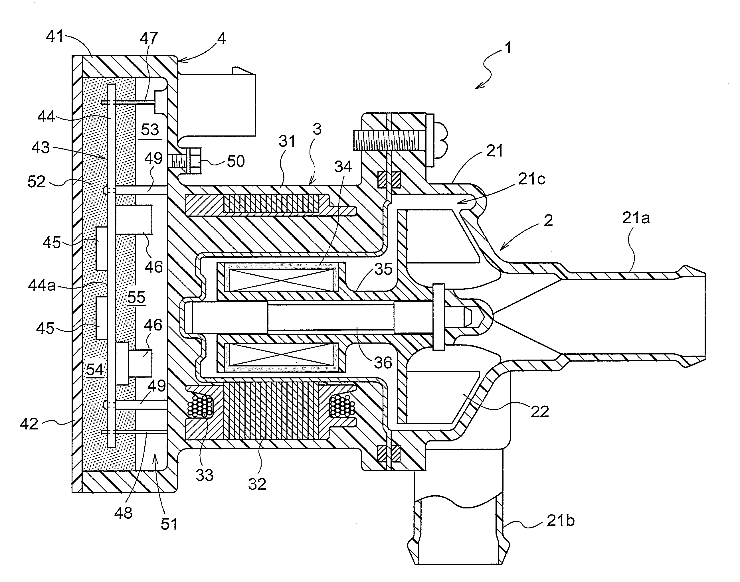
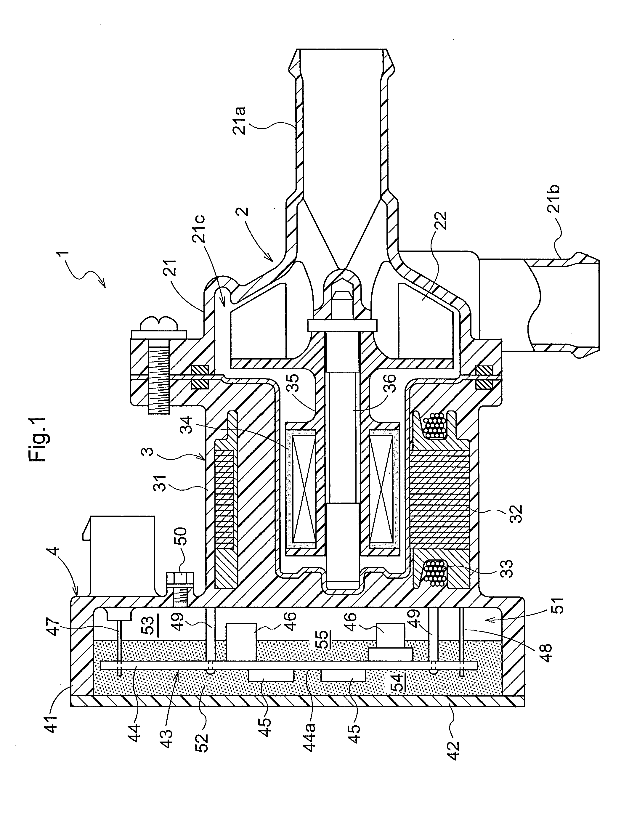
[0027]Next, embodiments of an electric pump relating to the present invention will be explained with reference to the accompanying drawings. As shown in FIG. 1, an electric pump 1 relating to this embodiment includes a pump unit 2, a motor unit 3 for driving the pump unit 2, and a driver chamber 4 having a driver 43 for controlling the motor unit 3.

[0028]A pump housing 21 accommodating the pump unit 2 is formed of resin; and a cylindrical inlet opening 21a and a cylindrical discharge opening 21b are formed in this housing 21. These inlet opening 21a and discharge opening opening 21b are communicated respectively to an impeller chamber 21c formed inside the pump housing 21. The impeller chamber 21c accommodates an impeller 22. In association with rotation of this impeller 22, an amount of fluid is introduced into the impeller chamber 21c via the inlet opening 21a and at the same time an amount of fluid is discharged from the impeller chamber 21c to the discharge opening 21b.

[0029]A ...


PUM


Abstract

To provide an electric pump that does not easily suffer malfunction of its driver due to vibration and whose components can be reduced in number, an electric pump includes a pump unit, a motor unit for driving the pump unit, and a driver chamber having a driver for controlling the pump unit. At least a space inside the driver chamber on one side of a substrate of the driver is filled with an amount of potting material for anchoring the substrate, whereas a space inside the driver chamber on the other side of the substrate is left as an unfilled space free from filling with potting material along the face direction of the substrate.

Description

TECHNICAL FIELD[0001]The present invention relates to an electric pump including a pump unit, a motor unit for driving the pump unit and a driver chamber having a driver for controlling the pump unit.BACKGROUND ART[0002]An example of the electric pump described above is known from Patent Document 1 for instance. With this electric pump, in order to promote heat discharge from the driver, a sheet-like heat discharging material is interposed between the driver and a cover of the driver chamber. With provision of this heat discharging material, heat of the driver is positively conducted via the heat discharging material to the cover to be air-cooled via this cover. As a result, heat discharge of the driver can be effected in an efficient manner.PRIOR ART DOCUMENTPatent Document[0003]Patent Document: Japanese Unexamined Patent Application Publication No. 2005-337095DISCLOSURE OF THE INVENTIONObject to be Achieved by Invention[0004]The driver substrate of this electric pump is fixed with...

Claims


Application Information

Patent Timeline
Patent Type & Authority Applications(United States)
IPC IPC(8): F04D13/06
CPCH02K5/128H02K11/0073F04D29/5893F04D13/0686F04D29/5813F04D13/06H02K11/33
Inventor SUGIMURA, KEITAKAWAJI, MANABU
Owner AISIN SEIKI KK
Why Eureka
Try Eureka