Single Wrapped Sensor Flow Meter

Active Publication Date: 2013-08-08
CIDRA CORP SERVICES
View PDF2 Cites 9 Cited by
  • Summary
  • Abstract
  • Description
  • Claims
  • Application Information

AI Technical Summary

Benefits of technology

[0022]Some advantages of the present invention include the fact that this technique disclosure proposes a method of measuring fluid flow within a pipe using as little as a single sensor (channel). This greatly simplifies the processing algorith

Problems solved by technology

The strain is a result of unsteady pr

Method used


Image

  • Single Wrapped Sensor Flow Meter
  • Single Wrapped Sensor Flow Meter
  • Single Wrapped Sensor Flow Meter

Examples


Embodiment Construction
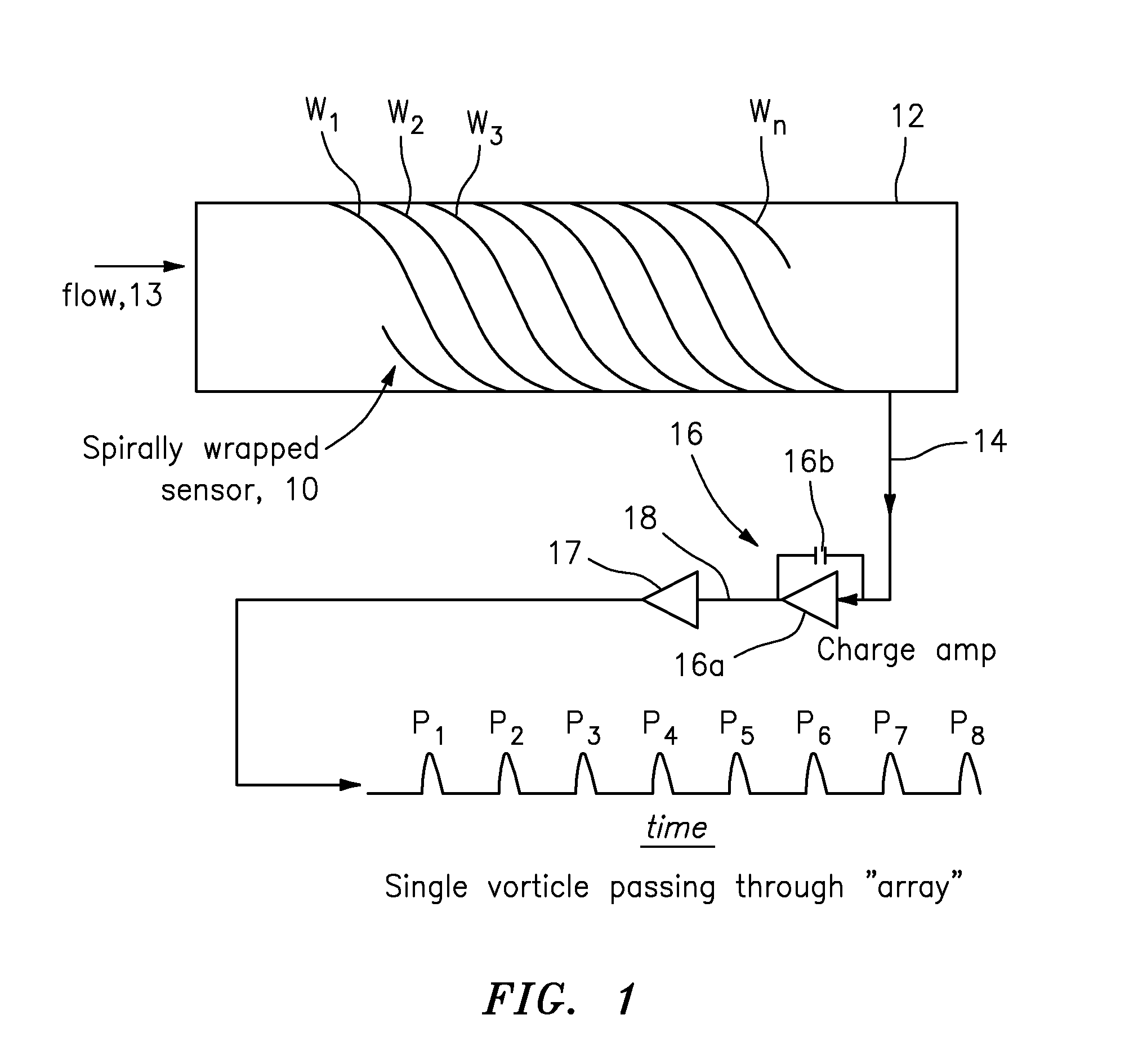
FIG. 1

[0031]FIG. 1 shows an embodiment according to the present invention in the form of a single piece of piezo-electric polymer sensor 10 that is spirally wound down a pipe 12 at a known pitch. In operation, a process flow 13 is moving along the pipe 12, and the piezo-electric polymer sensor 10 can sense a single localized vorticle passing down the pipe 12 and provide pulses along a signal path 14 that can be amplified by a charge amp generally indicated as 16, as shown, and other operational amplifier technology like element 17, as shown. For example, the charge amp 16 may include an operational amplifier 16a and a capacitor 16b, as shown. Based at least partly on an amplified output signal provided by the charge amp 16 along signal path 18 of the single localized vorticle passing down the pipe 12, a time delay between pulses p1, p2, p3, p4, p5, p6, p7, p8 represent the time required for the single localized vorticle to travel the distance between sensor wraps (pitch).

[0032]By wa...


PUM


Abstract

A signal processor receives a signal containing information about a sensor that is spirally wrapped at a known pitch or separation down a pipe having a flow; and determines a flow velocity based at least partly on the information contained in the signal received by applying an autocorrelation function that depends on a relationship between the time between a repeating pattern and the known pitch or separation of the spirally wrapped sensor. The signal processor provides a corresponding signal containing information about the flow velocity. The sensor includes a strain sensor, including a piezo-electric polymer strain sensor fabricated from PVDF, and/or two or more equally spaced spirally wound sensors. The determining includes correlating output signals of two or more equally spaced spirally wound sensors to determine a time delay, and determining the flow velocity based on the time delay and the known pitch or separation.

Description

CROSS-REFERENCE TO RELATED PATENT APPLICATIONS [0001]The present application claims the benefit of U.S. Provisional Patent Application No. 61 / 312,008, filed 9 Mar. 2010, which is incorporated by reference herein in its entirety.BACKGROUND OF THE INVENTION[0002]1. Technical Field[0003]This invention relates generally to measuring a parameter of a fluid and more particularly to a method and apparatus for measuring a parameter of a fluid such as velocity and volumetric flow rate of the flow within a pipe.[0004]2. Description of Related Art[0005]A fluid flow process (flow process) includes any process that involves the flow of fluid through pipes, ducts, or other conduits, as well as through fluid control devices such as pumps, valves, orifices, heat exchangers, and the like. Flow processes are found in many different industries such as the oil and gas industry, refining, food and beverage industry, chemical and petrochemical industry, pulp and paper industry, power generation, pharmace...

Claims


Application Information

Patent Timeline
IPC IPC(8): G01F1/66G01F1/7082
CPCG01F1/708G01F1/66G01F1/712G01F1/7082
Inventor FERNALD, MARK R.
Owner CIDRA CORP SERVICES
Why Eureka
Try Eureka