Eureka AIR delivers breakthrough ideas for toughest innovation challenges, trusted by R&D personnel around the world.

Zero backlash gear structure

Inactive Publication Date: 2013-08-08
NATIONAL CHUNG CHENG UNIV
View PDF33 Cites 20 Cited by
  • Summary
  • Abstract
  • Description
  • Claims
  • Application Information

AI Technical Summary

Benefits of technology

The present invention provides a zero backlash gear structure that improves the precision, stiffness, and cost-effectiveness of gear mechanisms. The helical angle difference between a spline and tooth form of a gear is used to cause a plurality of gears to make relative axial displacement by means of spline and gear shaft, so that when backlash occurs, an elastic element is used to make a plurality of gears on a compound gear set to get close to each other, eliminating gear transmission backlash, and high stiffness forward and reverse rotations. The structure can be applied to single pair and various planetary gears, and a flange can be provided at the bottom of a compound gear set to achieve the effect of zero backlash and zero torque transmission time difference.

Problems solved by technology

Firstly, stiffness of the overall structure is insufficient, in causing minute time difference between output torques, thus it is not suitable to use in large horse power transmission mechanism.
Secondly, during assembly, additional fixtures are required.
Thirdly, size of the structure is rather large requiring more components, manufacturing cost is high, assembly efficiency is insufficient.
In other words, presently, the gear backlash regulating and eliminating mechanism is not able to provide various advantages required for a gear pair simultaneously: zero time difference in torque transmission, high stiffness, wide application, low production cost, and easy assembly.
The first category is formed by two motors in cooperation with a rotary encoder to control precision of forward and reverse rotations, yet for this kind of mechanism, not only the cost is high, but it is not suitable to use for multi engaging-element pairs.
The second category is formed by a gear backlash eliminating mechanism, but this kind of mechanism has the problems that, when it is utilized in high torsion transmission, the reverse rotation of the mechanism could compress its displacement elastic element, to produce transmission angle delay, thus severely affecting overall performance of the mechanism.
In addition, for this kind of gear backlash elimination mechanism, it requires large number of components, its manufacturing process is complicated, and its cost is high, thus having the shortcomings of large stiffness difference for forward and reverse rotations, high production cost, and inferior assembly efficiency, hereby adversely affecting precision of forward and reverse rotations, and reducing its market competitiveness.
In the structure mentioned above, the stiffness of the overall structure is not sufficient for the large horse power transmission mechanism.
In addition, for this kind of design, during assembly, additional fixtures are required.
Therefore, presently, the design and performance of gear backlash eliminating mechanism is not quite satisfactory, and it has much room for improvements.

Method used


Image

  • Zero backlash gear structure
  • Zero backlash gear structure
  • Zero backlash gear structure

Examples


Embodiment Construction

[0020]The purpose, construction, features, functions and advantages of the present invention can be appreciated and understood more thoroughly through the following detailed description with reference to the attached drawings.

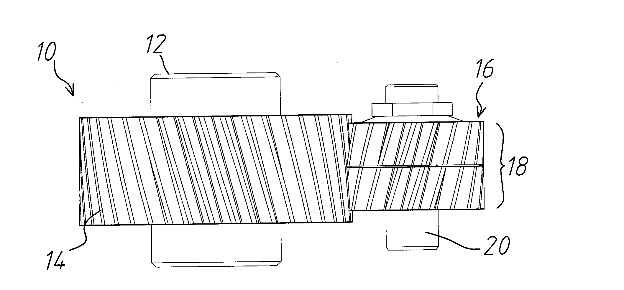
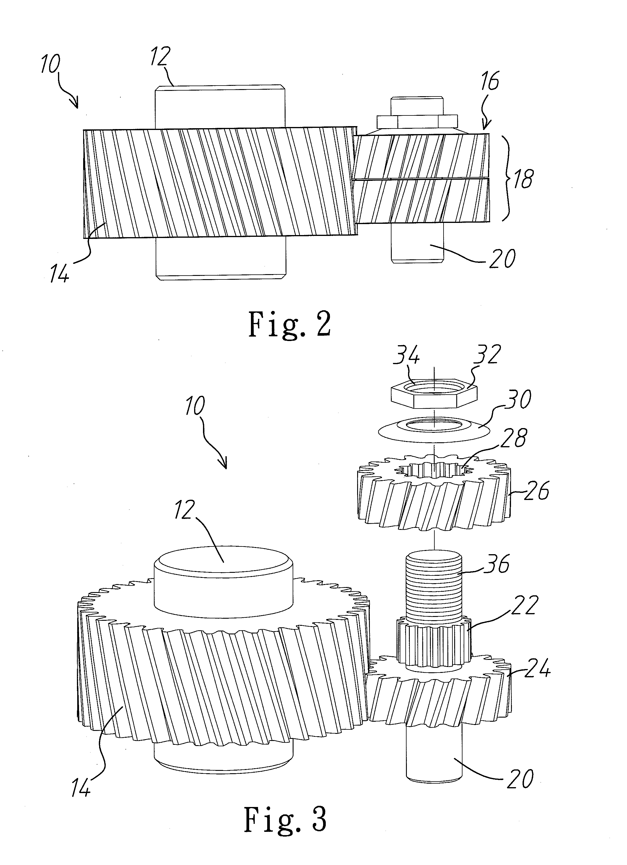
[0021]Refer to FIG. 2 for a schematic diagram of a zero backlash gear structure according to a first embodiment of the present invention; and FIG. 3 for an exploded view of a zero backlash gear structure according to a first embodiment of the present invention. As shown in FIGS. 2 and 3, the present invention provides a zero backlash gear structure 10, comprising at least an engaging element 12, a compound gear set 16, an elastic element 30, and a fixing element 32. Wherein, the engaging element 12 can be a gear or a gear rack (not shown), on the engaging element 12 is provided with a plurality of engaging slots 14, wherein, the engaging element 12 and the engaging slots 14 can be realized as components sleeved together or an integral workpiece. The compound ge...


PUM


Abstract

A zero backlash gear structure, comprising: an engaging element, a compound gear set, an elastic element, and a fixing element. Wherein, the engaging element is provided with a plurality of engaging slots. The compound gear set includes a compound gear, a gear shaft, and a spline; wherein, the compound gear is provided with at least two gears, said plurality of gears can be engaged to a plurality of engaging slots. Said fixing element is sleeved onto said gear shaft, to press against said plurality of gears and said elastic element. When backlash occurs, said elastic element is used to make said plurality of gears on said compound gear set to get close to each other automatically, so that said fixing element and said compound gear set can move in synchronism, thus achieving zero backlash in both forward and reverse rotations.

Description

BACKGROUND OF THE INVENTION[0001]1. Field of the Invention[0002]The present invention relates to a gear transmission structure, and in particular to a zero backlash gear structure.[0003]2. The Prior Arts[0004]In general, zero backlash gear is used extensively in high precision torque transmission mechanism, such as machine tool work-piece turning table. However, the conventional zero backlash gear structure has the following two shortcomings. Firstly, stiffness of the overall structure is insufficient, in causing minute time difference between output torques, thus it is not suitable to use in large horse power transmission mechanism. Secondly, during assembly, additional fixtures are required. Thirdly, size of the structure is rather large requiring more components, manufacturing cost is high, assembly efficiency is insufficient. As such, it can not be used to a single pair or multi-pair engaging elements. In other words, presently, the gear backlash regulating and eliminating mecha...

Claims


Application Information

Patent Timeline
IPC IPC(8): F16H55/18
CPCY10T74/19623F16H55/18F16D2001/103
Inventor FONG, ZHANG-HUACHEN, SZU-HUNG
Owner NATIONAL CHUNG CHENG UNIV
Why Eureka
Eureka Blog
Learn More