
Sensor-controlled system and method for electronic apparatus

a sensor-controlled system and electronic apparatus technology, applied in outdoor lighting, semiconductor devices of light sources, light and heating apparatus, etc., can solve the problems of interrupting reading, easy fatigue of the eyes of the reader, unnecessary energy waste, etc., and achieves user-friendly, high-accuracy sensor-controlled mechanism, and enhanced energy efficiency of electronic apparatus

Inactive Publication Date: 2013-08-08
EMINENT ELECTRONICS TECH
View PDF3 Cites 7 Cited by
  • Summary
  • Abstract
  • Description
  • Claims
  • Application Information

AI Technical Summary

Benefits of technology

The proposed sensor-controlled system controls the brightness of a light emitting unit of an electronic device to match the duration of a person's vision. When the light is turned off, the system uses sensors to detect reflected signals, recognize gestures, and monitor changes in ambient light. This highly accurate system allows for seamless brightness adjustment without flickering, resulting in enhanced energy efficiency and a more user-friendly and convenient experience.

Problems solved by technology

In addition, the LED fabrication process uses no material that can potentially cause the greenhouse effect contributing to global warming.
If the surrounding light intensity is decreased and the reader forgets to adjust the brightness of the light, the reader's eyes will get tired easily.
If the surrounding light intensity is increased and the reader forgets to adjust the brightness of the light, this leads to unnecessary energy waste even though the light is a LED lighting fixture.
The need for constant manual brightness adjustment will interrupt the reading and lower the user's enjoyment.

Method used


Image

  • Sensor-controlled system and method for electronic apparatus
  • Sensor-controlled system and method for electronic apparatus
  • Sensor-controlled system and method for electronic apparatus

Examples


Embodiment Construction

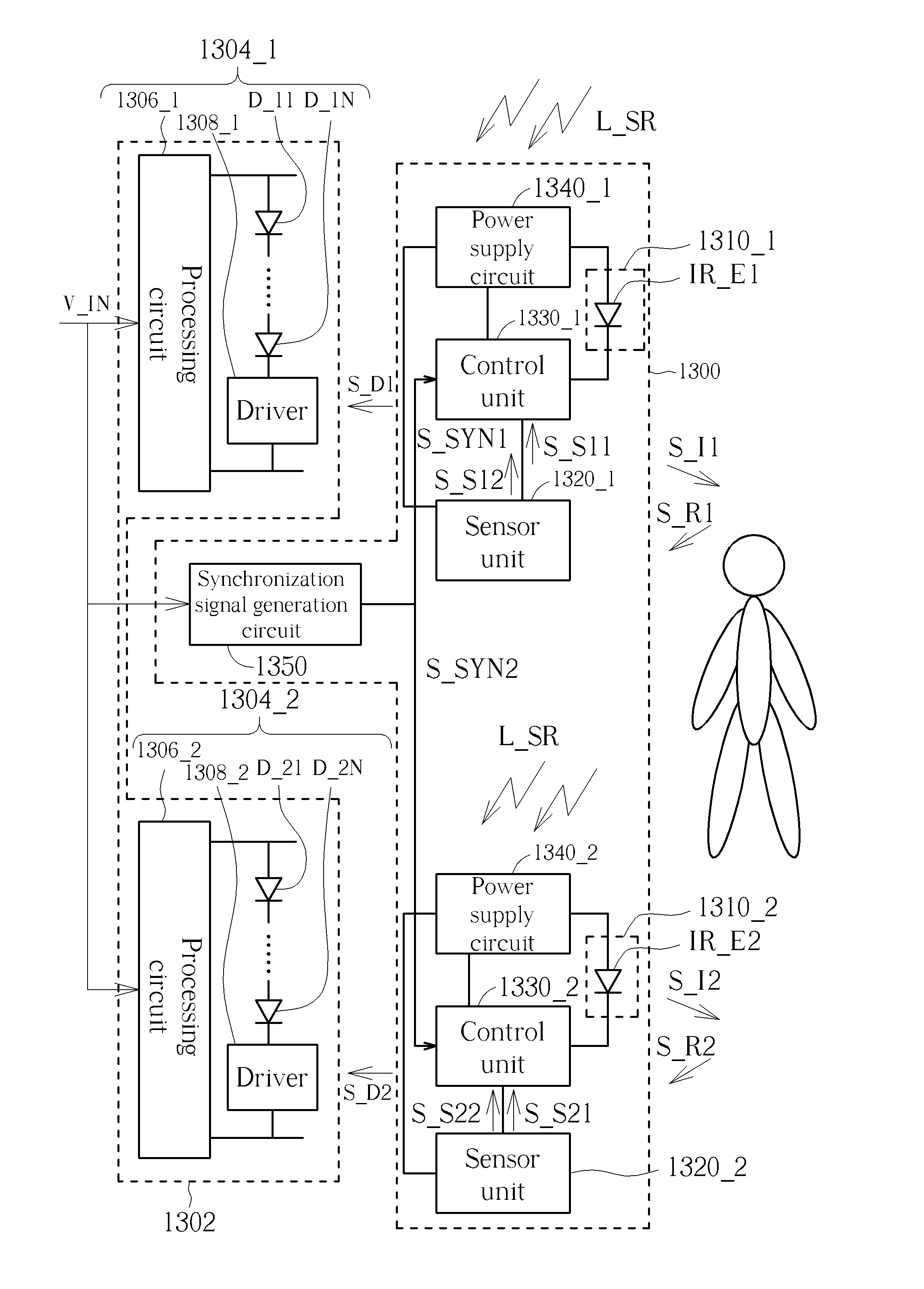
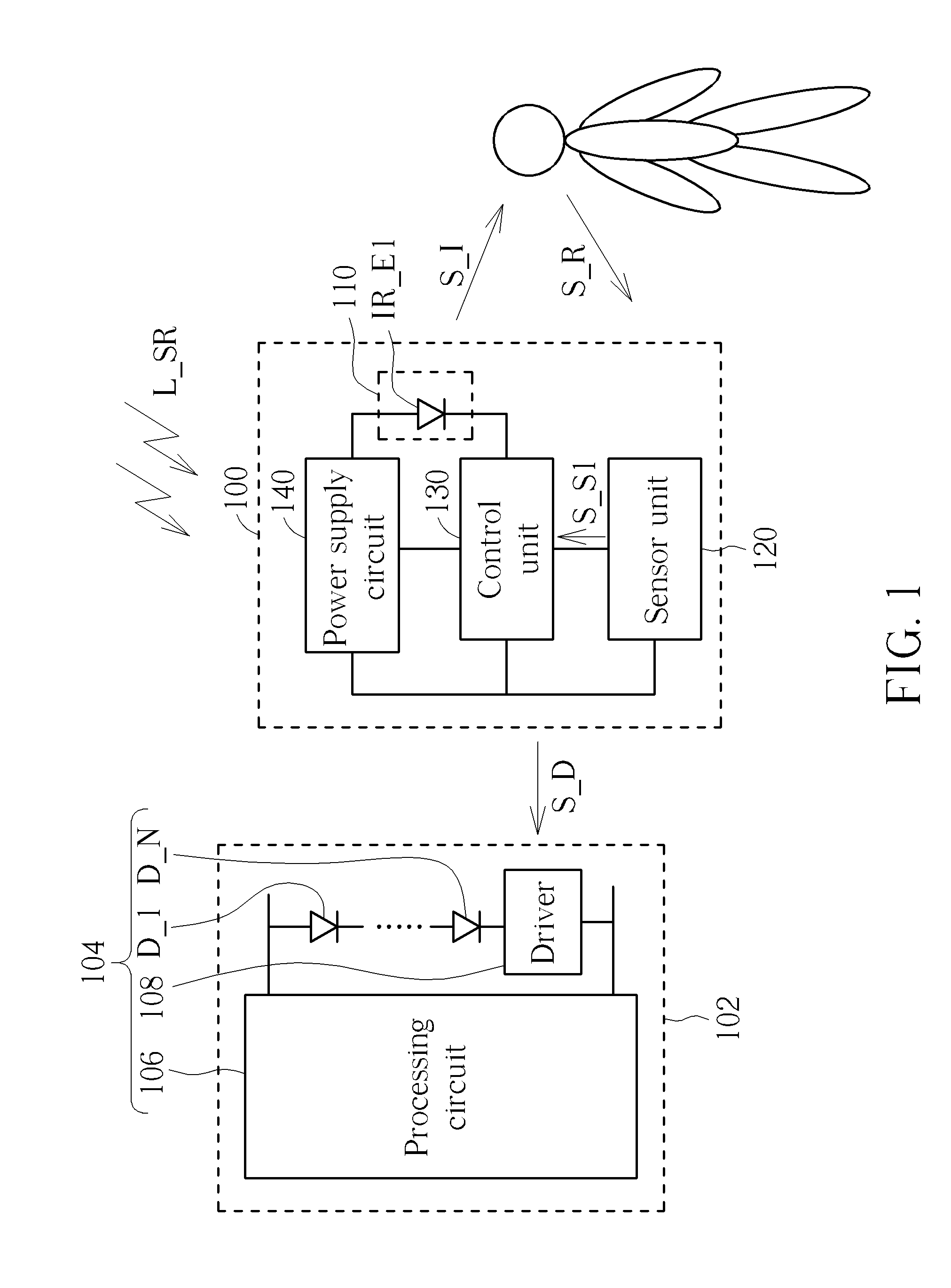
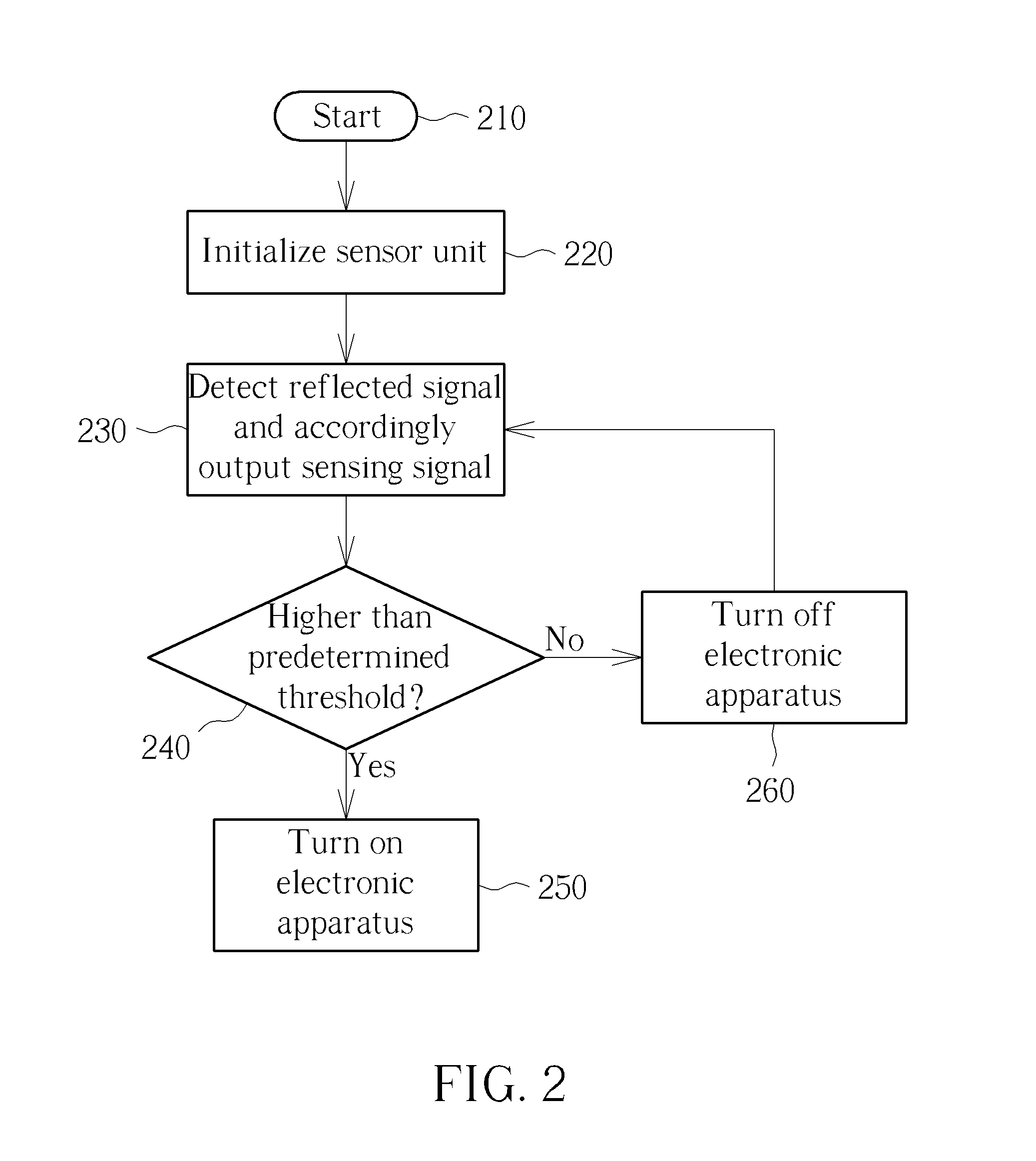
[0033]The proposed sensor-controlled system may be employed by any electronic apparatus having turn-on and turn-off operations. In a case where an activated electronic apparatus has a light-emitting function, the proposed sensor-controlled system may further adjust luminous intensity thereof. For clarity and brevity, the following embodiments are described with reference to the control of lighting fixtures. However, a person skilled in the art should understand that the applications of the present invention are not limited thereto.

[0034]Please refer to FIG. 1, which is a diagram illustrating an exemplary sensor-controlled system 100 for an electronic apparatus 102 according to an embodiment of the present invention. The sensor-controlled system 100 may control the electronic apparatus 102 according to reflected signals reflected from a human body. In this embodiment, the electronic apparatus 102 is a light emitting diode (LED) lighting fixture including a light emitting unit 104. Th...


PUM


Abstract

A sensor-controlled system for an electronic apparatus is provided. The electronic apparatus includes at least one light emitting unit. The at least one light emitting unit operates at an emission state and a non-emission state alternately. The sensor-controlled system includes at least one sensor unit and at least one control unit. The at least one sensor unit is arranged for sensing surrounding luminance to generate a sensing signal during a period in which the at least one light emitting unit operates at the non-emission state. The at least one control unit is coupled to the at least one sensor unit, and is arranged for controlling luminous intensity of the at least one light emitting unit according to the sensing signal.

Description

BACKGROUND OF THE INVENTION[0001]1. Field of the Invention[0002]The disclosed embodiments of the present invention relate to a sensor-controlled system, and more particularly, to a sensor-controlled system capable of turning on an electronic apparatus and adjusting luminous intensity of the electronic apparatus according to surrounding luminance, and a related method.[0003]2. Description of the Prior Art[0004]Compared to incandescent lights and most fluorescent lights, light emitting diodes (LEDs) exhibit higher photoelectric conversion efficiency. In addition, the LED fabrication process uses no material that can potentially cause the greenhouse effect contributing to global warming. As a result, the LED is a necessary light source to achieve energy efficient lighting.[0005]Electronic lighting fixtures (e.g. LED lighting fixtures) need mechanical control devices for activation, deactivation and brightness adjustment. For example, when reading in a study, a reader may turn a control...

Claims


Application Information

Patent Timeline
Patent Type & Authority Applications(United States)
IPC IPC(8): F21V23/04
CPCF21V23/0464F21V23/0471F21Y2101/02H05B33/0803F21W2131/103F21S6/002F21Y2115/10H05B45/30H05B47/11Y02B20/40
Inventor CHANG, TOMWU, KAO-PINFANG, CHIH-JENHUNG, SHANG-MINGLIU, FANG-YU
Owner EMINENT ELECTRONICS TECH
Learn More