Phase frequency detector and charge pump for phase lock loop fast-locking

Active Publication Date: 2013-08-08
MEDIATEK INC
View PDF3 Cites 3 Cited by
  • Summary
  • Abstract
  • Description
  • Claims
  • Application Information

AI Technical Summary

Benefits of technology

[0015]A method and system in accordance with the present invention provides for a performing solution benefitting from providi

Problems solved by technology

However, such approaches of bandwidth extension typically require a boost to t

Method used


Image

  • Phase frequency detector and charge pump for phase lock loop fast-locking
  • Phase frequency detector and charge pump for phase lock loop fast-locking
  • Phase frequency detector and charge pump for phase lock loop fast-locking

Examples


Embodiment Construction

[0031]The following description is presented to enable one of ordinary skill in the art to make and use the invention and is provided in the context of a patent application and its requirements. Various modifications to the preferred embodiments and the generic principles and features described herein will be readily apparent to those skilled in the art. Thus, the present invention is not intended to be limited to the embodiments shown, but is to be accorded the widest scope consistent with the principles and features described herein.

[0032]FIG. 3A illustrates a phase frequency detector circuit 300 in accordance with an embodiment of the present invention. In FIG. 3A, a PFD circuit is provided 300 where a reference clock signal (CKref) 310 is inputted to a first flip-flop 315 and the output of a normal down pulse of the first flip flop 315 is provided as input to a first delay element 320 coupled with the first flip-flop 315. The first delay element 320 provides a plurality of delay...


PUM


Abstract

The present invention provides for a solution to reduce locking time with satisfactory performance without the need for significant footprint area for the phase lock loop (PLL) circuits by boosting phase frequency detector (PFD) and charge pump (CP) gains through various circuitry configurations that employ one or more flip-flops, delay elements and advanced circuitry techniques.

Description

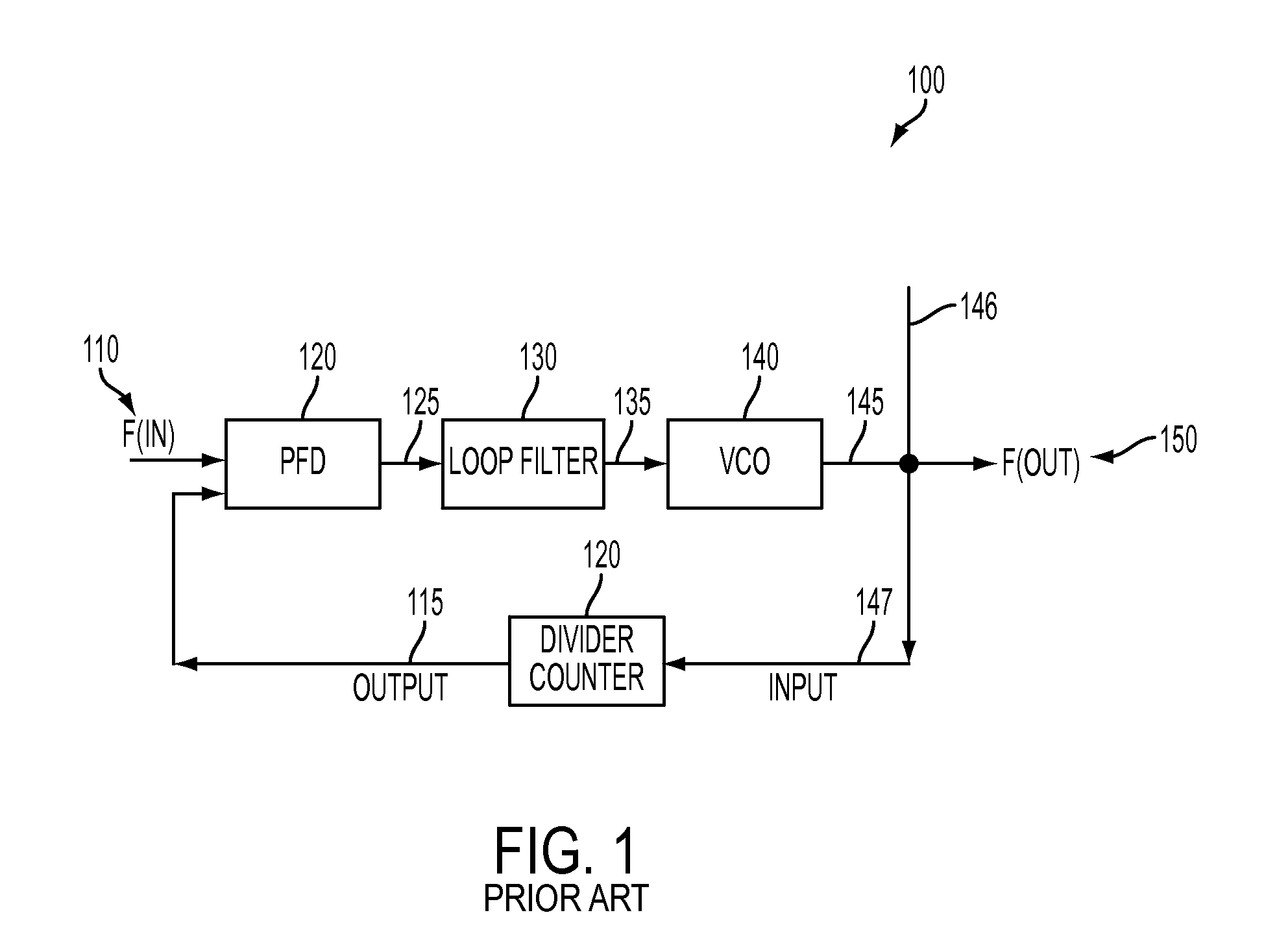
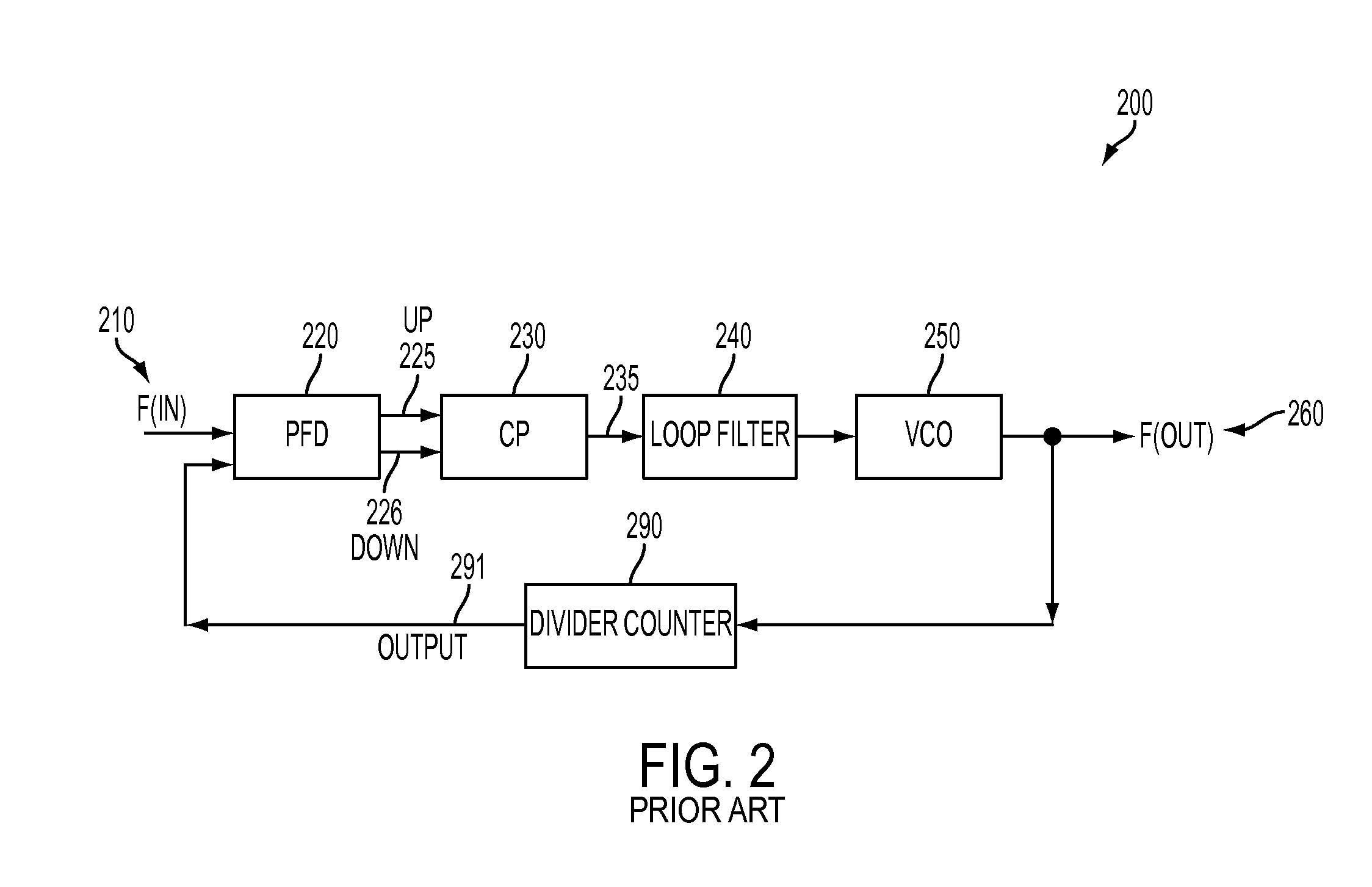
CROSS-REFERENCE TO RELATED APPLICATION[0001]This application claims the benefit of U.S. Provisional Patent Application No. 61 / 593,974, filed on Feb. 2, 2012, entitled “PHASE FREQUENCY DETECTOR AND CHARGE PUMP FOR PHASE LOCK LOOP FAST-LOCKING,” which is incorporated herein by reference in its entirety.FIELD OF THE INVENTION[0002]The present invention relates generally to the efficient use of phase lock loop (PLL) circuits, and more particularly to phase frequency detectors (PFDs) and charge pumps (CPs).BACKGROUND OF THE INVENTION[0003]Phase Locked Loops (PLL) circuits are electronic circuits that provide for a variable frequency oscillator (VCO) and a phase / frequency detector (PFD) which generate an output signal having a phase that is associated with the phase of an input signal to the PLL. Typically, the PLL attempts to generally provide for phase matching as between the phases of the input signal and the output signal by adjusting the frequency of the VCO based on control signals ...

Claims


Application Information

Patent Timeline
IPC IPC(8): H03L7/089
CPCH03L7/0891H03L7/10H03L7/1072H03L7/0896
Inventor HSUEH, YU-LIZHAN, JING-HONG CONAN
Owner MEDIATEK INC
Why Eureka
Try Eureka