Composite structural element, particularly for a vehicle suspension, and method for manufacturing the same

a technology of composite structural elements and vehicle suspensions, which is applied in the field of composite structural elements, can solve the problems of excessive slaps, limits to the freedom of designers in designing cross-sections, and excessive increase in so as to achieve high mechanical properties and reduce the overall weight of the element

Active Publication Date: 2013-08-15
SISTEMI SOSPENSIONI SPA
View PDF13 Cites 19 Cited by
  • Summary
  • Abstract
  • Description
  • Claims
  • Application Information

AI Technical Summary

Benefits of technology

[0012]In short, the invention is based on the idea of providing a structural element comprising a shell and a core, wherein the shell is made of at least one layer of composite material comprising a fibre-reinforced polymeric matrix and wherein the core is made of a ductile material (in particular, of metal). In the following description and claims, the term “shell” is to be intended as referring to any kind of body defining at least one cavity, wherein such a body may be formed indifferently by a single piece or by several pieces joined to each other and may indifferently have either a closed cross-section or an open cross-section (in which case, naturally, the shell is not a flat element). The simultaneous presence of a material having high mechanical properties (material of the shell) and of a ductile material (material of the core) allows to meet at the same time the opposite requirements for “fatigue” life, reaction load, modality of deformation, and presence of a “deformation witness” mark under “limit load” conditions. The “fatigue” life and the reaction load under “limit load” conditions are ensured, in particular, by the high-strength material of the shell, and, in this connection, the shell is suitably shaped to provide the element with the “inertia” characteristics required each time by the specific application. The ability to absorb impact energy, the ability to provide a “deformation witness” mark, and tire ability to avoid failures (such as to lead to the separation of parts) are ensured, on the other hand, by the due tile material of the core. The use of composite material for the shell of the structural element, which forms the main portion of the structural element in terms of volume of material clearly allows to reduce the overall weight of the element with respect to the prior art.

Problems solved by technology

Such a known solution is, however, affected by the drawback that the use of the over-moulding technique to produce the plastic material portion of the structural element makes It possible to obtain only structural elements with a solid cross-section.
This inevitably involves limits to the freedom of the designer in designing the cross-section of the element, which limits are excessively penalizing, for instance, in case of structural elements intended to be used for triangular suspension arms.
As is known, in order to increase the strength of the structural element, it is necessary to increase the moment of inertia of the cross-section thereof [in other words, to shift the material of the cross-section as far as possible from the middle plane thereof (in the present case, from the metal core), which results in an excessive increase in the overall weight of the element].
Also, these structural elements suffer from the same drawback discussed above with reference to U.S. Pat. No. 7,159,880.

Method used


Image

  • Composite structural element, particularly for a vehicle suspension, and method for manufacturing the same
  • Composite structural element, particularly for a vehicle suspension, and method for manufacturing the same
  • Composite structural element, particularly for a vehicle suspension, and method for manufacturing the same

Examples


Embodiment Construction

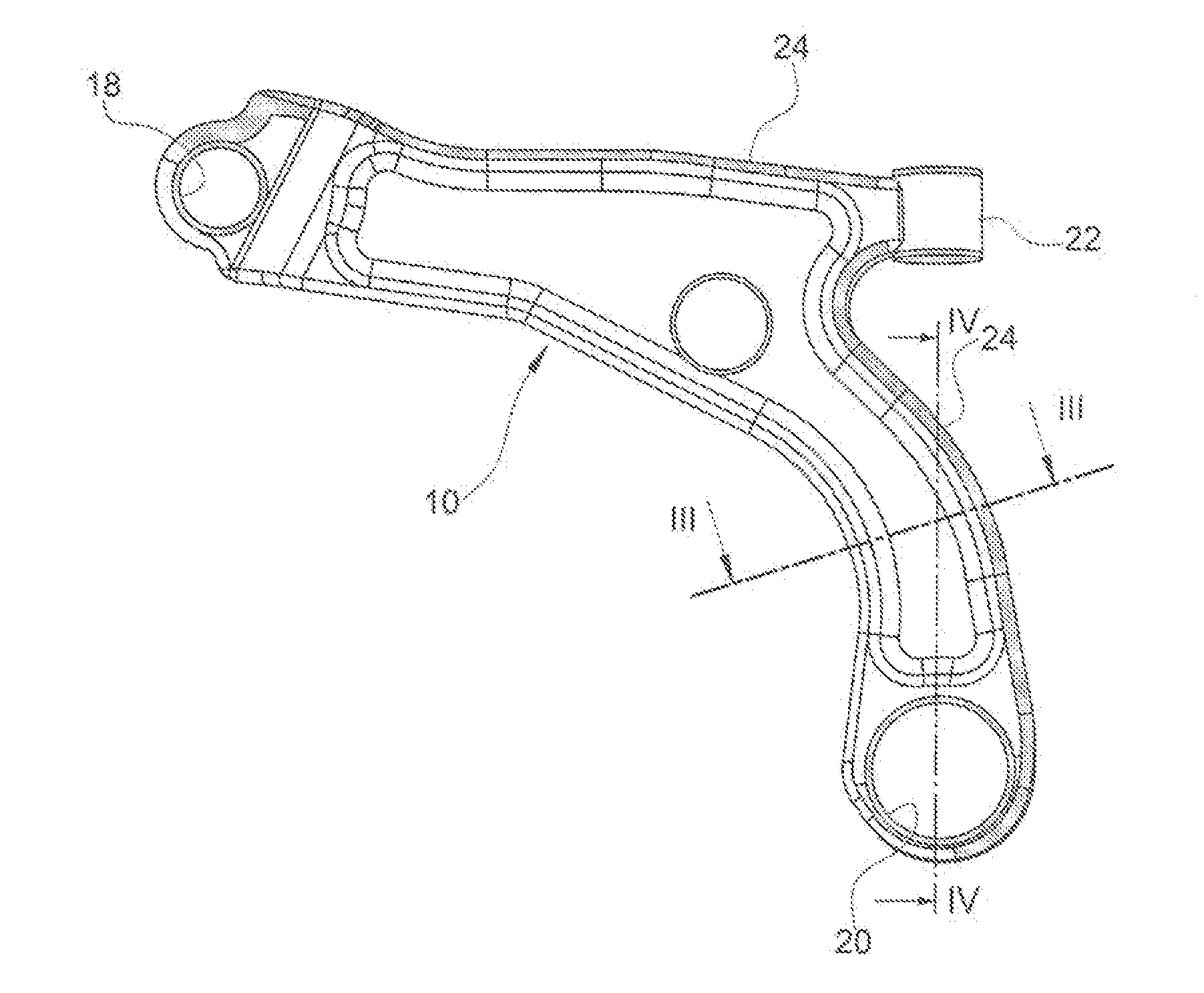
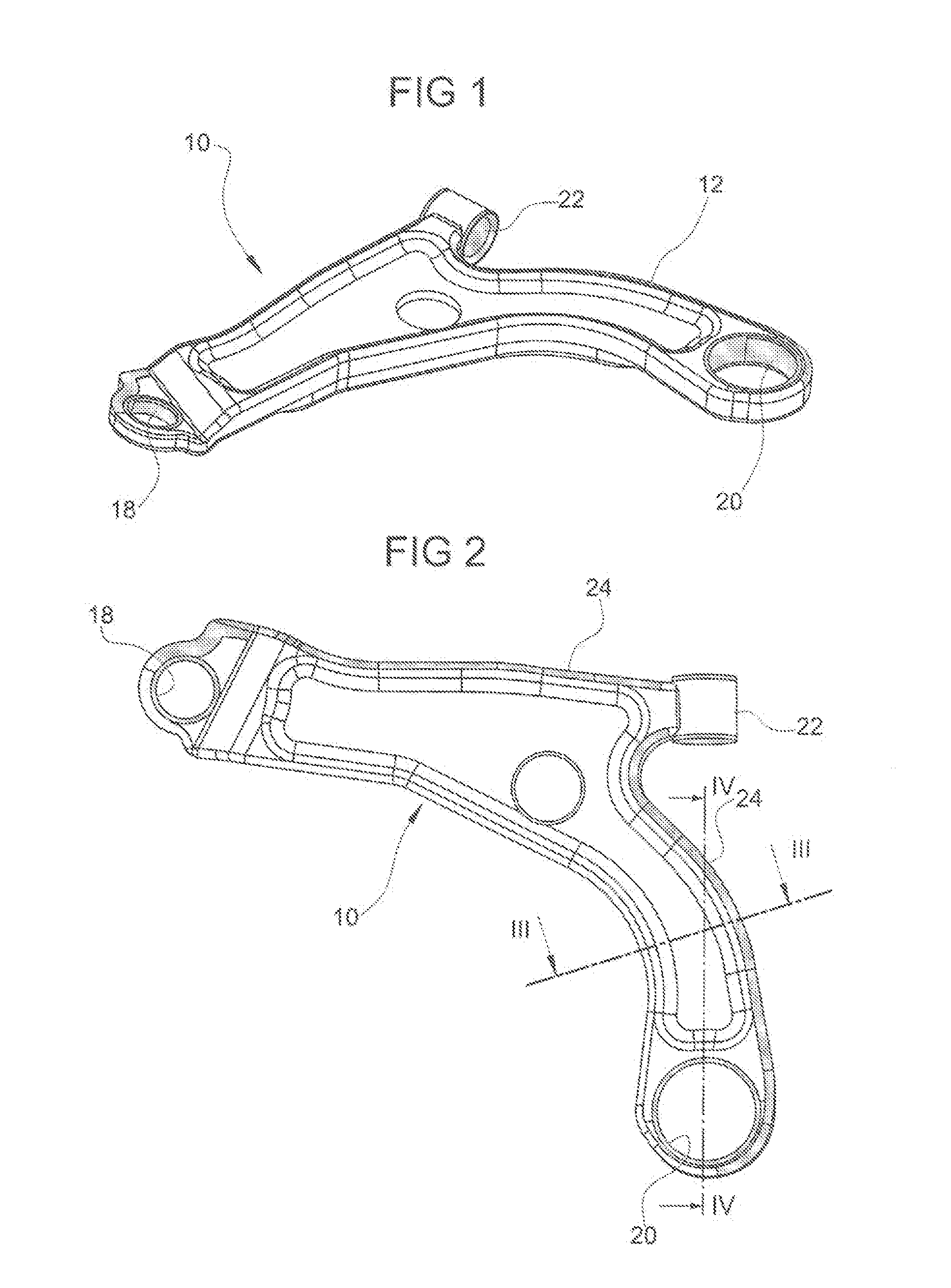
[0022]With reference first to FIGS. 1 to 4, “10” generally indicates a triangular arm for a motorcar suspension as an example of a structural element according to the invention. However, the invention is applicable to any other structural element for a vehicle, not necessarily an element intended to be used as a suspension component.

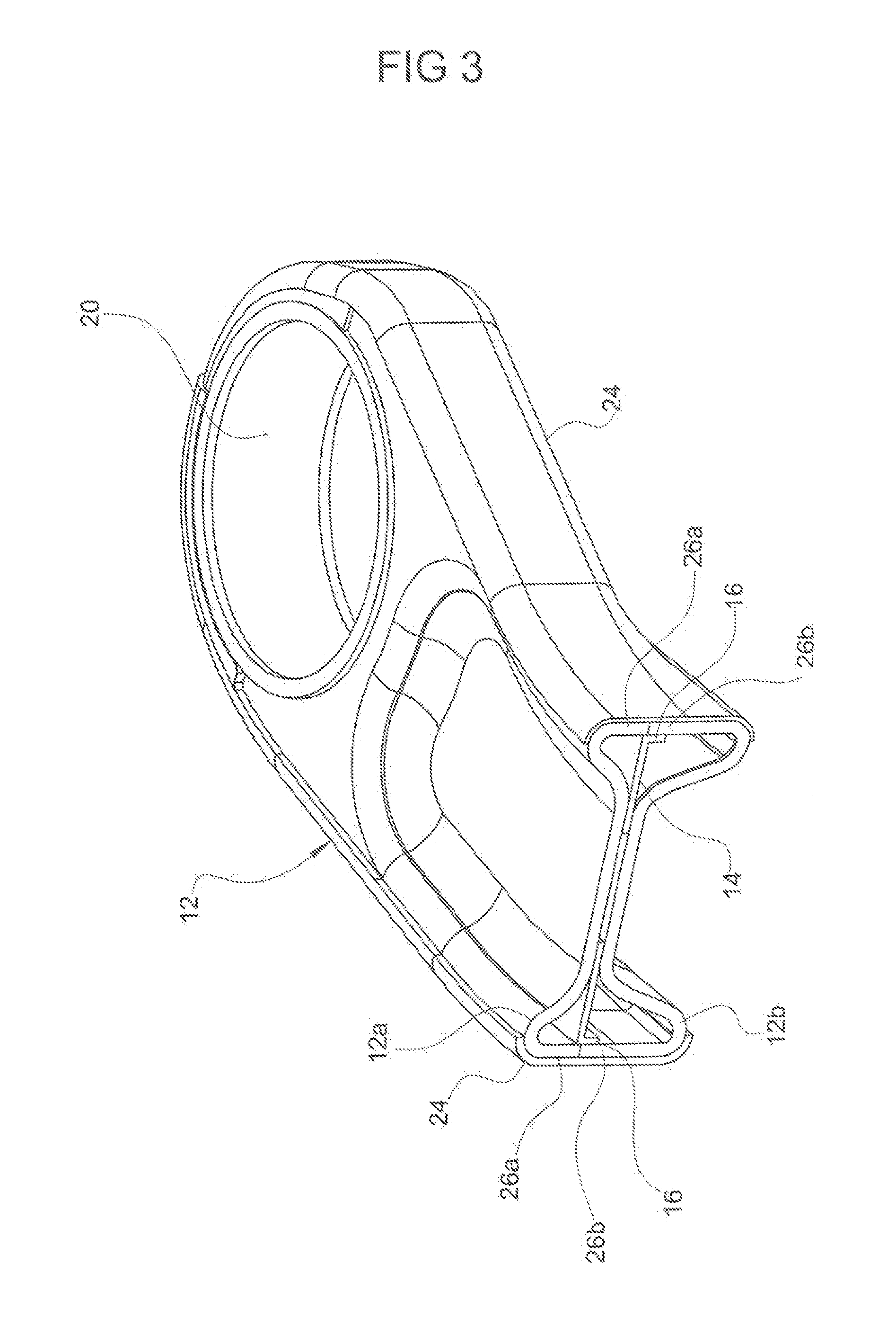
[0023]The arm 10 basically comprises a shell 12 of composite material, a core 14 (FIGS. 3 and 4) of ductile material, and a plurality of seats (in the present case, three seats) for receiving each a respective connection member (not shown), such as a bush or a ball joint, for connection of the arm, on the one hand, to a wheel-carrier (not shown) and, on the other hand, to the vehicle body (also not shown).

[0024]The shell 12 is a body that, is shaped so as to define at least one cavity and, in particular (in the example illustrated in the drawing), is a hollow body having a closed cross-section. The shell 12 is made of at least one layer of composite mate...


PUM

PropertyMeasurementUnit
temperatureaaaaaaaaaa
weightaaaaaaaaaa
stiffnessaaaaaaaaaa

Abstract

A method for manufacturing a structural element comprises steps of providing separate first and second half-shells made of at least one layer of composite material including a fibre-reinforced polymeric matrix, providing a core made of ductile material Joking the core to the first half-shell such that at least one cavity is defined inside the structural element, and joining the second half-shell to the first half-shell.

Description

CROSS-REFERENCE TO RELATED APPLICATIONS[0001]This application claims priority to PCT Patent Application PCT / EP2011 / 057676 entitled “Composite Structural Element, Particularly for a Vehicle Suspension, and Method for Manufacturing the Same” and filed on May 12, 2011, which claims benefit of the filing date of Italian Patent Application TO2010A000395 filed on May 12, 2010.BACKGROUND OF INVENTION[0002]1. Field of Invention[0003]The invention relates, generally, to a composite structural element and, particularly, to such an element for use in a vehicle suspension as well as a method for manufacturing the element.[0004]2. Description of Related Art[0005]The materials generally used in mass production of components for vehicle suspensions, such as motorcar suspensions, are steel, cast iron, and aluminium for reasons due to costs of production and performances of the material (weight, stiffness, “fatigue” life, resistance to limit load conditions, etc.). The use of composite materials for...

Claims


Application Information

Patent Timeline
Patent Type & Authority Applications(United States)
IPC IPC(8): B60G7/00
CPCB29C65/02Y10T29/49622B29C66/5414B29C66/721B29C66/742B29C66/74283B29D24/002B60G7/001B60G2200/1424B60G2206/013B60G2206/10B60G2206/122B60G2206/30B60G2206/60B60G2206/7101B60G2206/7105B60G2206/722B60G2206/82B60G2206/821B62D29/001E04C3/28B62D29/004B29C65/48
Inventor SANTINI, ANDREAMONCHIERO, PIEROBORGNA, GUIDO
Owner SISTEMI SOSPENSIONI SPA
Why Eureka
Try Eureka