Processing method and system for high-temperature solid steel slag

a processing method and high-temperature solid steel technology, applied in the field of processing methods and processing systems for high-temperature solid steel slag, can solve the problems of poor fluidity, inability to easily pour out slag ladles, and high dust emission, so as to facilitate mating and sealing, reduce the amount of investment, and increase the operating rate of the traveling crane

Active Publication Date: 2013-08-15
BAOSHAN IRON & STEEL CO LTD
View PDF0 Cites 8 Cited by
  • Summary
  • Abstract
  • Description
  • Claims
  • Application Information

AI Technical Summary

Benefits of technology

[0024]In a preferable embodiment, the seal door is a curved plate and disposed at the material feeding port, the curvature of the seal door is equal to the curvature of the side surface of the material feeding barrel, the engaging surface of the seal door with the material feeding port is conical, i.e., larger at outside and smaller at inside, so as to facilitate the mating and sealing of both; the seal door can be lifted and dropped easily by the robot on the movable trolley.
[0025]The above-mentioned steel slag processing method adopts a method of “one-time slag feeding, gradual processing”, and changes the existed method of “processing while slag feeding”, so that it not only increases the operating rate of the traveling crane, but also eliminates the slag ladle titling device and the slag removal device required by high-viscosity slag processing. It not only reduces the massive invest, but also highly increases the producing efficiency, so that it can rapidly process high-viscosity slag, especially blocky high-temperature steel slag such as ladle-bottom slag.
[0026]The above-mentioned steel slag processing device adopts a dual-cavity serial structure with a material feeding barrel and a working barrel, changes the existed single-process-cavity processing cylinder, adds a material feeding / stocking cavity at one side of the process cavity, and smartly achieves an axial feeding and flowing of slag material within the barrel by means of a spiral motion produced by an inclination angle and a cylinder rotation. It not only solves the technical bottle-neck of ladle-bottom slag feeding, but also achieves a processing method of “integral material feeding, gradual processing”.

Problems solved by technology

Due to the differences among various steel companies' steelmaking processes, the compositions and temperatures of steel slag produced during smelting are not completely identical: some high-temperature steel slag has an excellent fluidity, so that it can be poured out like water; some high-temperature steel slag has a poor fluidity, so that it cannot be easily poured out from a slag ladle (a container for containing and transporting high-temperature steel slag, also called as a slag basin), can only be poured out from the slag ladle by means of mechanical external force or slag ladle inversion.
This portion of slag is either held in the slag ladle, or poured out in a whole from the slag ladle, so that a suitable mechanical crushing is necessary for a subsequent processing, and dust emission is very serious.
Its shortcoming is that the processing subject of this method is limited strictly, i.e., only steel slag having an excellent fluidity can be processed, and steel slag having a higher viscosity and a poor fluidity cannot be processed.
The method is relatively simple, can achieve a massive processing for steel slag; however, its shortcomings are also very obvious: in view of safety, this method can only process blocky steel slag having a temperature lower than 800° C., so that hotter steel slag should firstly be cooled outside of the hot stuffing pool, during which, it is necessary to turn over the steel slag repeatedly in order to increase the producing efficiency, causing a serious dust emission and thermal pollution.
Its shortcoming is that the current rolling cylinder device cannot achieve a cleaning processing to ladle-bottom slag.

Method used


Image

  • Processing method and system for high-temperature solid steel slag
  • Processing method and system for high-temperature solid steel slag
  • Processing method and system for high-temperature solid steel slag

Examples


Embodiment Construction

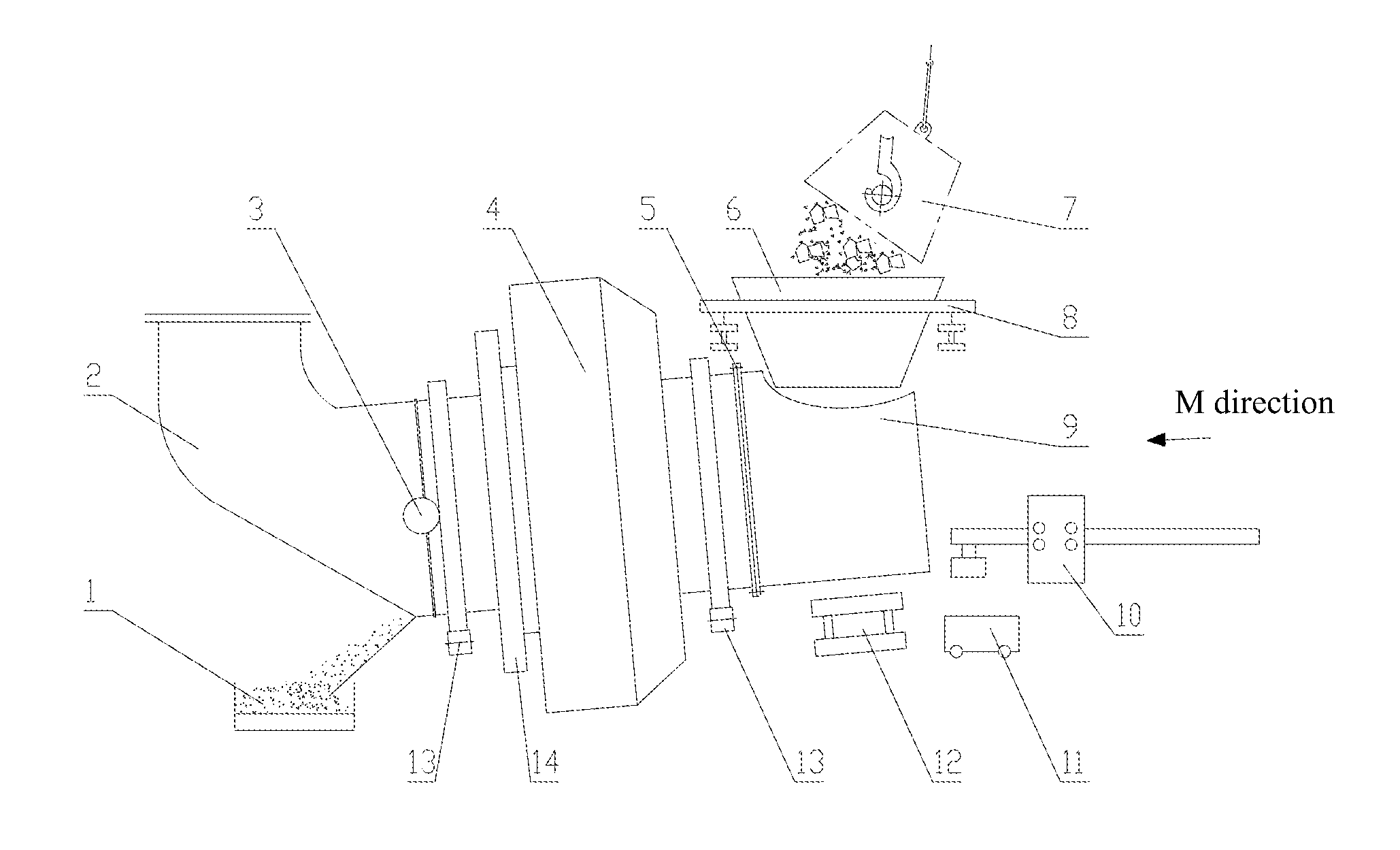
[0038]Hereinafter, the present disclosure will be further explained in connection with figures and particular embodiments. The below-mentioned working barrel and its mating supporting, driving devices can be implemented and modified according to the slag processing device in rolling cylinder method disclosed in WO2006 / 024231.

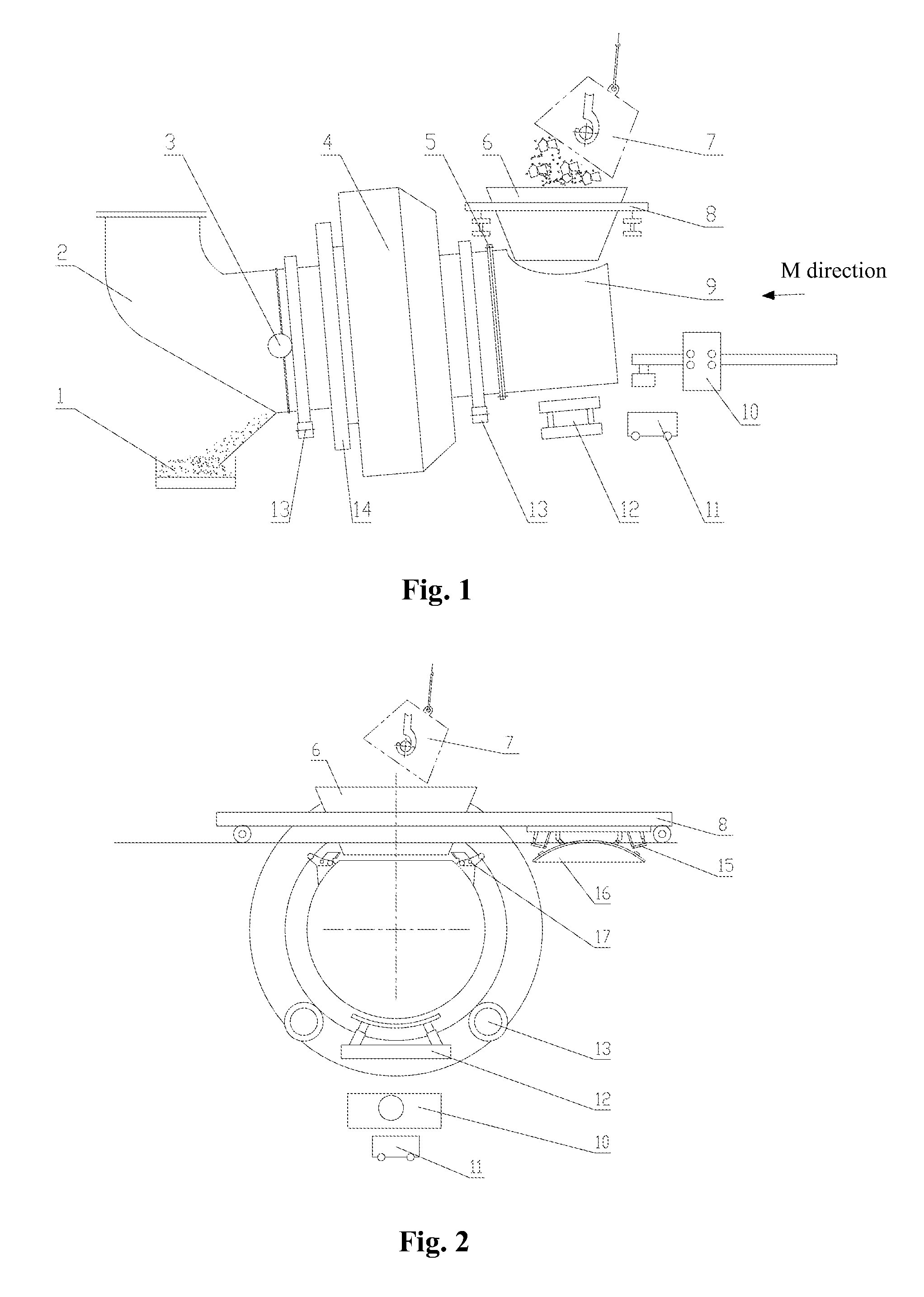
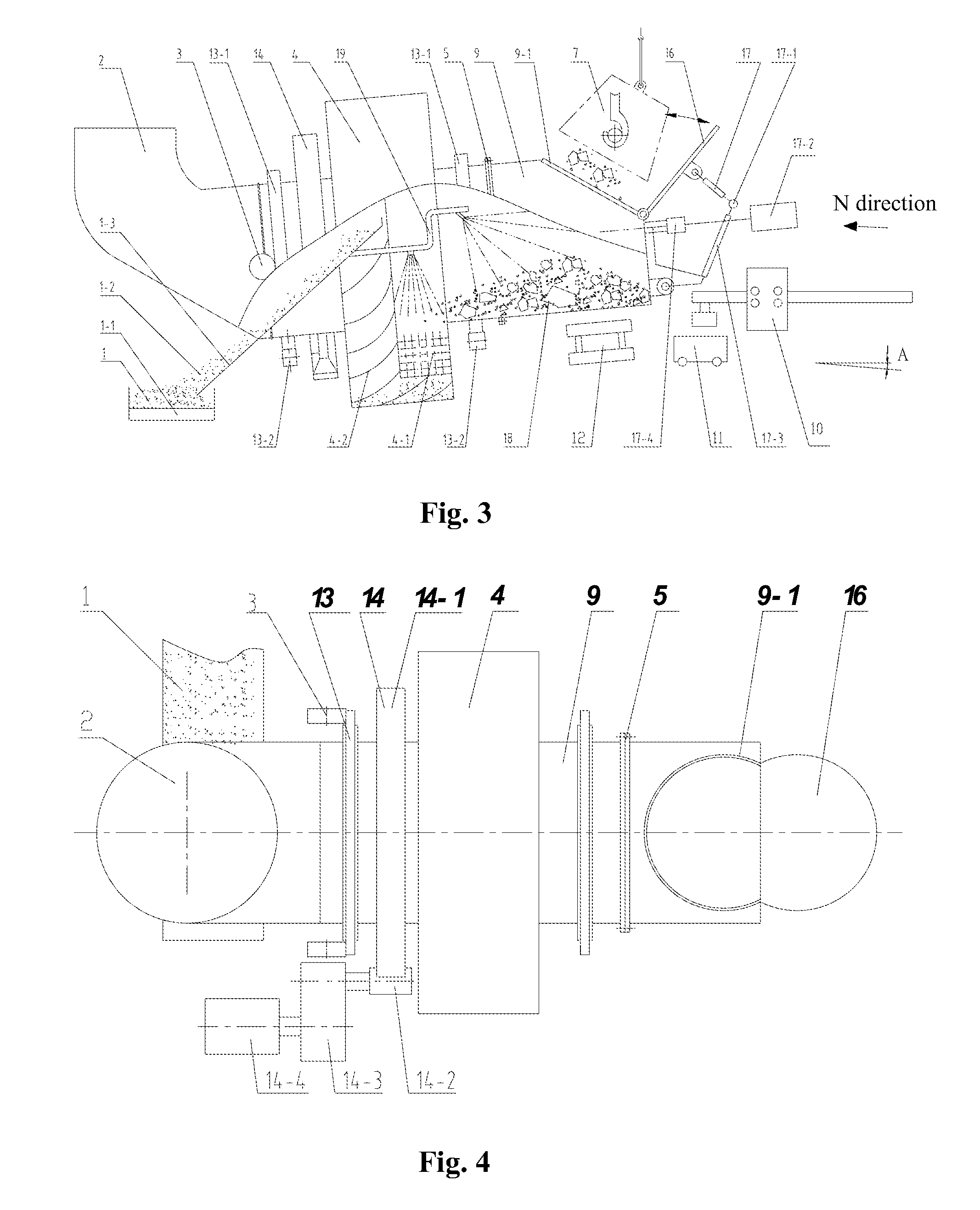
[0039]FIGS. 1-8 show a processing method for high-temperature solid steel slag, wherein a material feeding barrel 9, which can contain adequate high-temperature solid steel slag, is mounted in the front of a working barrel 4, a material feeding port 9-1 and an automatic open / close seal door 16 are located on a side surface of the material feeding barrel 9, the material feeding barrel 9 is coaxially and rigidly secured to the working barrel 4 by a flange 5, and the axis has an upward inclination angle A with respect to the horizontal plane; angle A is 0˜20°.

[0040]Cooling and crushing medium 4-1, i.e., steel balls, is disposed within the working barrel 4, for rapi...


PUM

PropertyMeasurementUnit
temperatureaaaaaaaaaa

Abstract

A system for disposing high temperature solid state steel slag includes a working barrel (4), a feeding barrel (9), a liftable hydraulic bracket (12), a supporting device(13) and a transmission device(14). The working barrel (4) axially connects with the feeding barrel (9) in series. The working barrel (4) is provided with cooling and crushing medium (4-1) and spray pipe inside. A method for disposing high temperature solid state steel slag by using said system enables single feeding and multiple disposing.

Description

TECHNICAL FIELD[0001]The disclosure relates to a processing method and a processing system for high-temperature solid steel slag.BACKGROUND ART[0002]Steel slag is an inevitable byproduct of steelmaking process, and is approximately 10% to 15% of the steel yield, therefore, the rapid and effective processing for steel slag, especially for high-temperature steel slag, directly influences the common run of steelmaking process and the sustainable development of steel companies. Due to the differences among various steel companies' steelmaking processes, the compositions and temperatures of steel slag produced during smelting are not completely identical: some high-temperature steel slag has an excellent fluidity, so that it can be poured out like water; some high-temperature steel slag has a poor fluidity, so that it cannot be easily poured out from a slag ladle (a container for containing and transporting high-temperature steel slag, also called as a slag basin), can only be poured out...

Claims


Application Information

Patent Timeline
Patent Type & Authority Applications(United States)
IPC IPC(8): B02C17/04
CPCB02C17/04C21B3/08C21B2400/052C21B2400/056
Inventor XIAO, YONGLILI, YONGQIANLIU, YINCUI, JIAN
Owner BAOSHAN IRON & STEEL CO LTD
Why Eureka
Try Eureka