Method for Testing Leakage Current or Electric Compressor

Active Publication Date: 2013-08-15
SANDEN CORP
View PDF4 Cites 1 Cited by
  • Summary
  • Abstract
  • Description
  • Claims
  • Application Information

AI Technical Summary

Benefits of technology

The present invention provides a method for testing the leakage current of an electric compressor. This method reduces the total test time required for a full test compared to using only one acceptance reference current value. Additionally, the method ensures the same level of test accuracy as if all test products were tested using the same reference current value.

Problems solved by technology

Freon-based coolant and ether-based or ester-based lubricating oil which are commonly used are dielectrics, and hence, a leakage current from the coil to the housing through the coolant or the lubricating oil is likely to be generated.
Furthermore, in a process of manufacturing the electric compressor, when the motor is installed and fixed to the housing, the coil of the motor may get damaged, and this damage may cause a large leakage current.
The leakage current may flow to a control unit that controls driving elements such as an engine, a brake, and a power steering through a vehicle body, adversely affect control, and lead to a serious accident by causing the driving element to malfunction.

Method used


Image

  • Method for Testing Leakage Current or Electric Compressor
  • Method for Testing Leakage Current or Electric Compressor
  • Method for Testing Leakage Current or Electric Compressor

Examples


examples

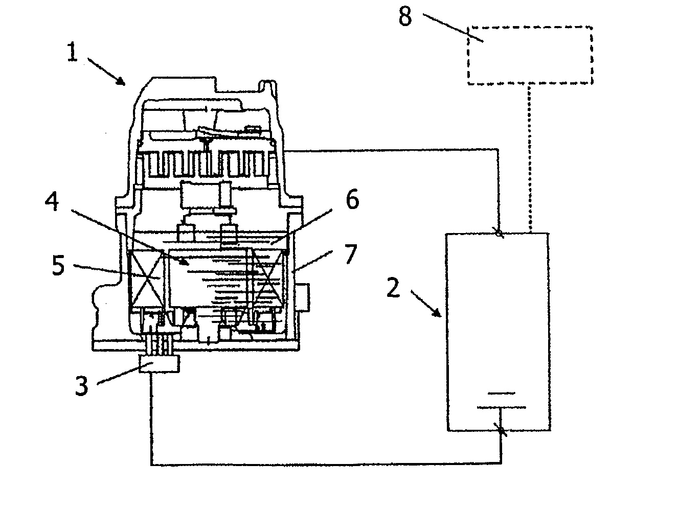
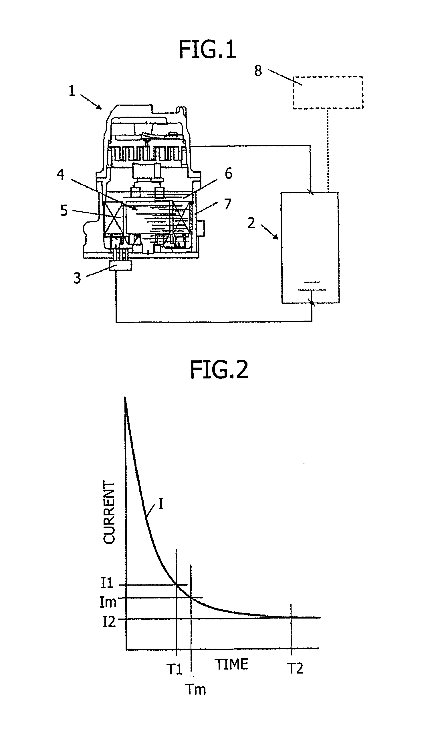
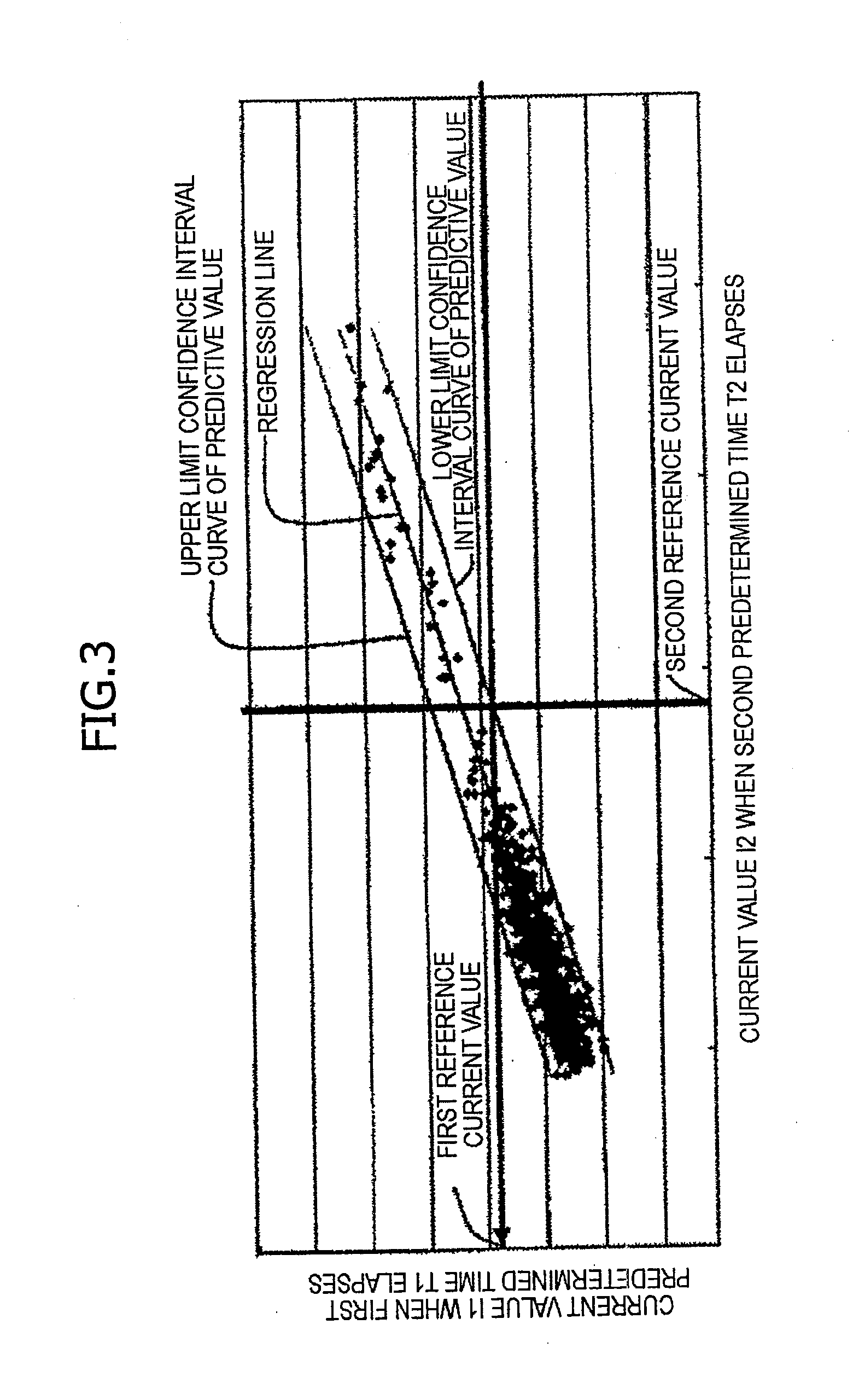
[0024]In order to collect statistical basic data collection, 620 factory products of electric compressors were prepared as samples. Polyalkylene glycol-based lubricating oil (moisture content 150 ppm) was used as dielectric liquid, the inside of the electric compressor of each sample was filled with the lubricating oil, and the entire coil of the motor was immersed below the liquid level of the lubricating oil. In this state, an applied voltage of a DC voltage 500 V was applied from the current meter between the coil and the housing of the compressor, and the current value I1 when the first predetermined time T1 elapses, the current value Im when the predetermined intermediate time Tm elapses, the current value I2 (a leakage current value) when the second predetermined time T2 elapses were measured on the current flowing from the coil to the compressor. In this measurement, the first predetermined time T1 was set to 180 seconds, the predetermined intermediate time Tm was set to 240 ...


PUM


Abstract

According to the present invention, after a predetermined voltage is applied to a coil in a state in which the inside of an electric compressor is filled with dielectric liquid and the coil of a motor is immersed in the dielectric liquid, in a first test process, a test product in which a current value when a first predetermined time T1 elapses I1 is less than or equal to a first reference current value is determined as an acceptable product, in a second test process, among the test products in which the current value is greater than the first reference current value in the first test process, a test product in which a current value I2 when a second predetermined time T2 longer than the first predetermined time elapses is less than or equal to a second reference current value is determined as an acceptable product, a test product in which the current value is greater than the second reference current value is determined as a disqualified product, and the first reference current value is a predictive reference current value that allows a test product which is to be determined as a disqualified product in the second test process to be determined as a disqualified product in the first test process, and allows some test products which are to be determined as an acceptable product in the second test process to be determined as a disqualified product in the first test process.

Description

TECHNICAL FIELD[0001]The present invention relates to a method for testing a leakage current of an electric compressor to test whether or not a leakage current leaking from a coil of a motor of an electric compressor to a housing is a reference value or less.BACKGROUND ART[0002]A high insulation treatment is performed between a coil of a motor of an electric compressor and a housing accommodating the motor so that a leakage current is not generated under a contact environment with air; however, when the compressor is in operation, the coil and the inside of the housing are exposed to a contact environment of coolant and lubricating oil. Freon-based coolant and ether-based or ester-based lubricating oil which are commonly used are dielectrics, and hence, a leakage current from the coil to the housing through the coolant or the lubricating oil is likely to be generated. Furthermore, in a process of manufacturing the electric compressor, when the motor is installed and fixed to the hou...

Claims


Application Information

Patent Timeline
IPC IPC(8): G01R31/34
CPCG01R31/025G01R31/34G01R31/52
Inventor ISHIHARA, MITSUGU
Owner SANDEN CORP
Why Eureka
Try Eureka