Antenna System with Small Multi-Band Antennas

a multi-band antenna and antenna technology, applied in the direction of antennas, antenna details, electrical equipment, etc., can solve the problems of limited power consumption at the installation location, high cost of renting/leasing space for the array, and often installed three-dimensional arrays of antennas. to achieve the effect of maximizing the number of antennas

Active Publication Date: 2013-08-15
CHARTER COMM OPERATING LLC
View PDF11 Cites 7 Cited by
  • Summary
  • Abstract
  • Description
  • Claims
  • Application Information

AI Technical Summary

Benefits of technology

[0005]When capturing over the air content with arrays of antennas, it is important to maximize the number of antennas at the installation location. One way to maximize the number of antennas is to create a three dimensional array of antennas. The three dimensional array is created by implementing two dimensional arrays on antenna array cards, and then installing multiple antenna array cards in close proximity to create the three dimensional array.
[0006]One issue is that the three dimensional arrays of antennas often are installed in or on buildings or towers where there are size and / or weight limitations. Additionally, many of the arrays will be installed in large metropolitan cities where the cost of renting / leasing space for the arrays is expensive. Furthermore, there are often power consumption limitations at the installation locations. Reducing the size of each individual antenna and also the power consumption of the supporting circuitry for the arrays make the system less costly to deploy, maintain, and operate.
[0007]Another benefit of having an array with numerous small antennas is redundancy. If an antenna fails (or multiple antennas fail), then one of the other antennas is able to replace the non-functioning antenna without disrupting service.
[0009]By implementing multi-band antennas, a wider frequency reception is achieved and a greater density of antennas is possible within the antenna array. Generally, the multi-band antennas are constructed from at least two electrically small loop antenna elements. Operation is based on the out of band impedance of the antenna elements. A tuning feed network is implemented with resistors, capacitors, varactors, inductors, or ferrite beads to control the tuning frequency of each antenna element. Additionally, each antenna is multiply resonant. This enables each antenna to have optimal performance and provide filtering of adjacent signals and / or avoid interference from signals that may be in the same band as the desired signal.

Problems solved by technology

One issue is that the three dimensional arrays of antennas often are installed in or on buildings or towers where there are size and / or weight limitations.
Additionally, many of the arrays will be installed in large metropolitan cities where the cost of renting / leasing space for the arrays is expensive.
Furthermore, there are often power consumption limitations at the installation locations.

Method used


Image

  • Antenna System with Small Multi-Band Antennas
  • Antenna System with Small Multi-Band Antennas
  • Antenna System with Small Multi-Band Antennas

Examples


Embodiment Construction

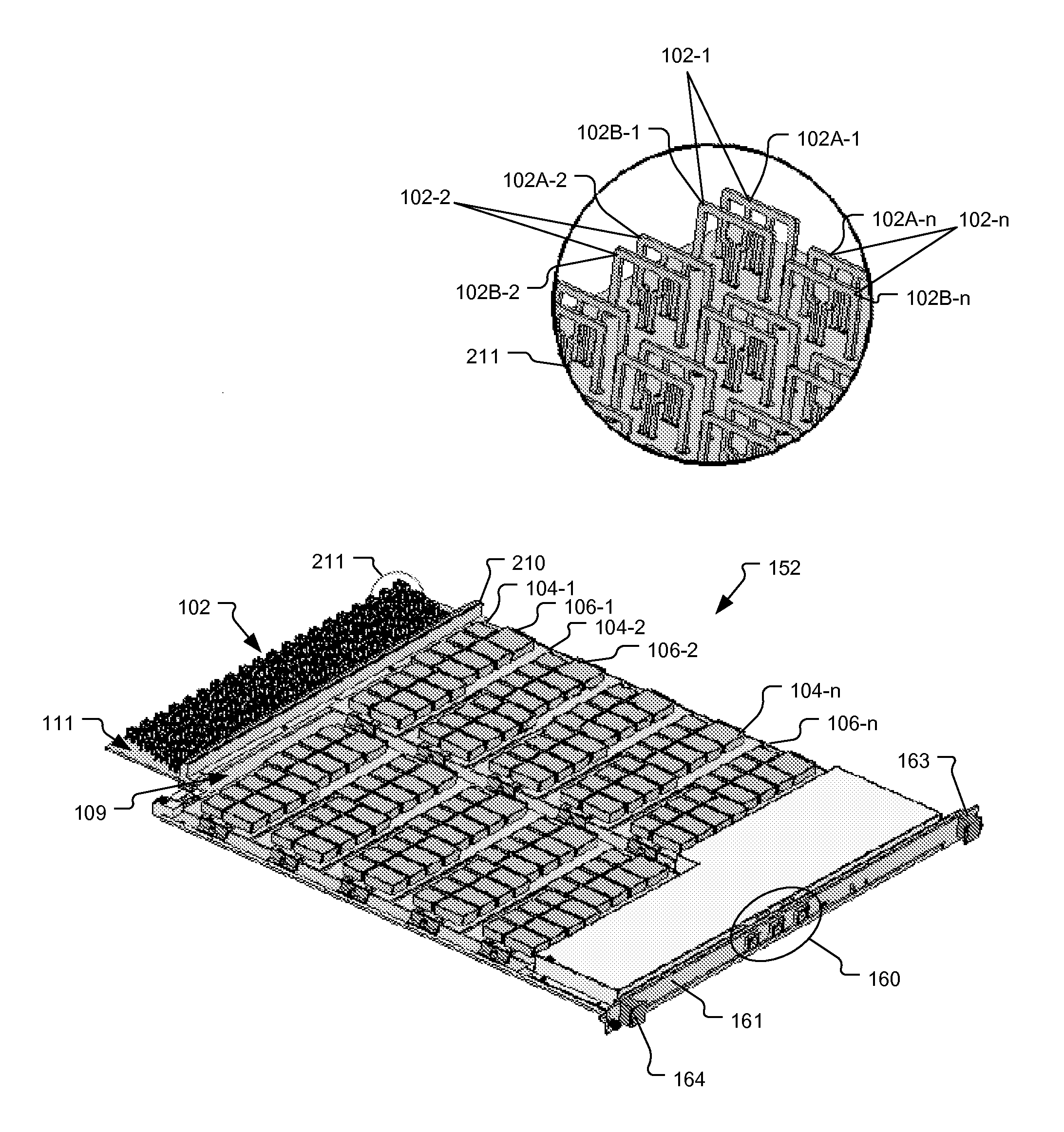
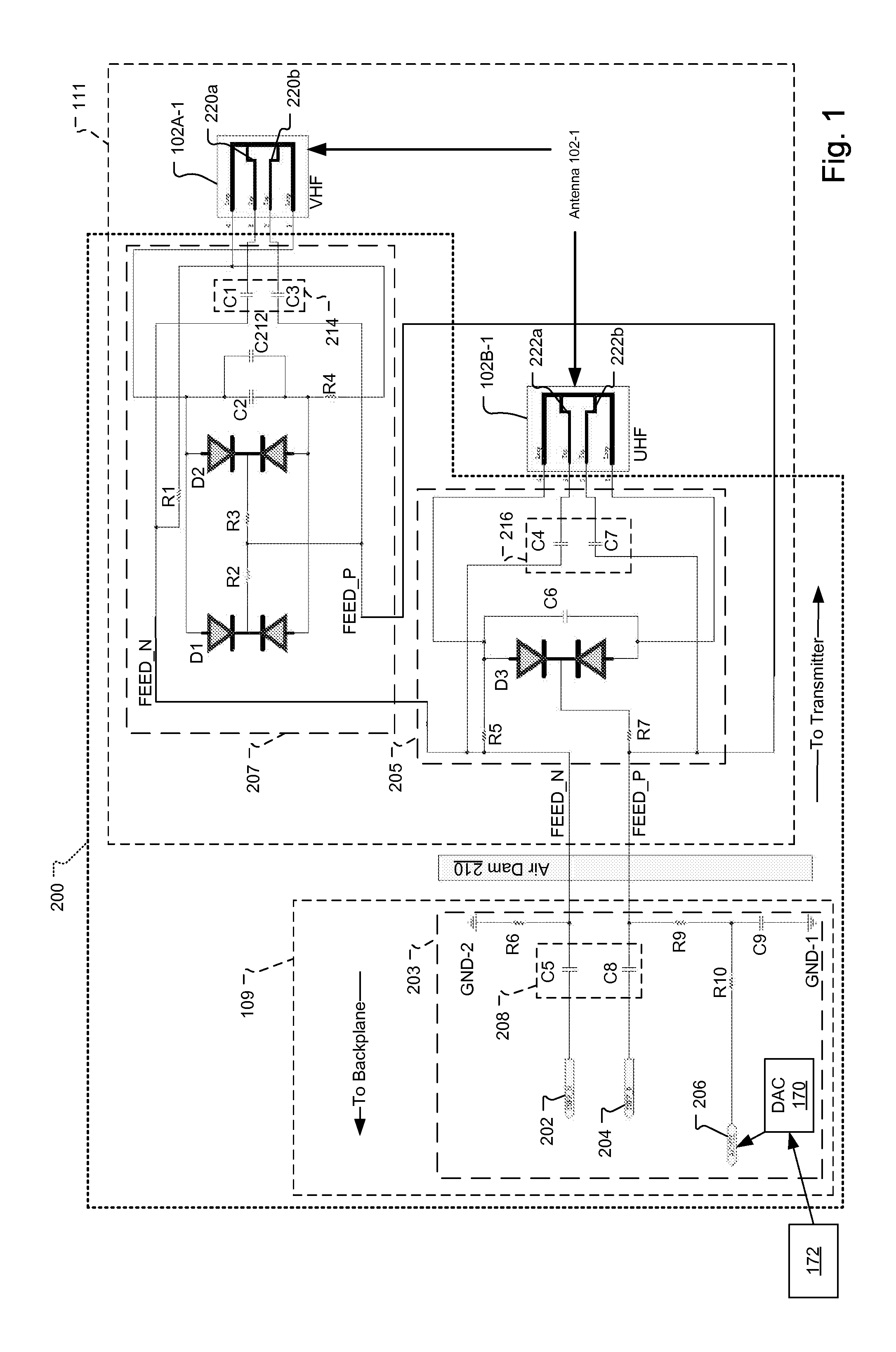
[0020]FIG. 1 is a circuit diagram of a multi-band antenna 102-1 and tuning feed network 200 for an antenna system, which has been constructed according to the principles of the present invention.

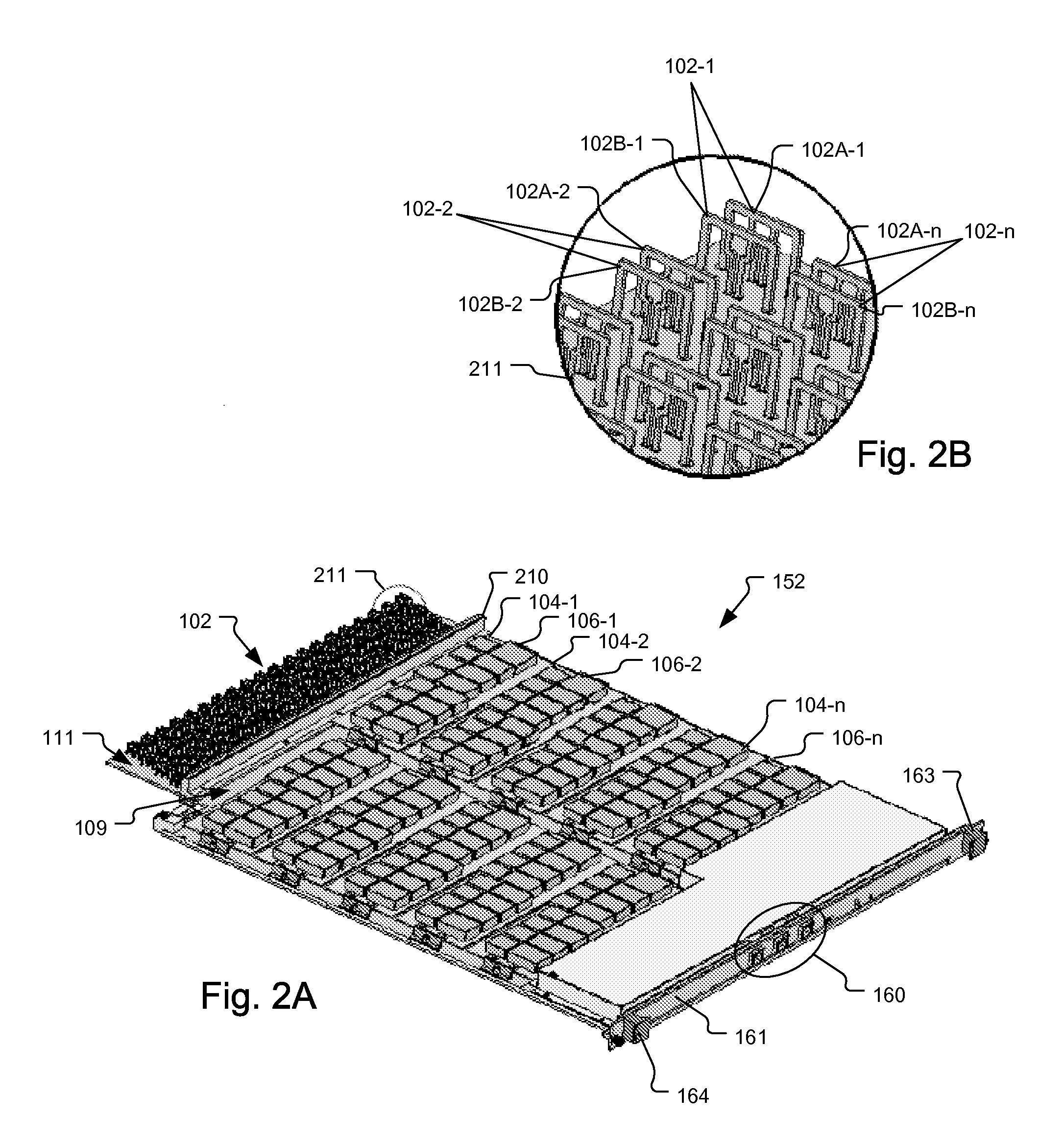
[0021]In the illustrated circuit diagram, the multi-band antenna 102-1 is shown as a dual band antenna, which is also referred to as an antenna element pair. In the illustrated example, the antenna 102-1 further includes a low frequency antenna element 102A-1 and a high frequency antenna element 102B-1. In alternative embodiments, however, additional antenna elements could be implemented to form a tri-band antenna or a multi-band antenna with three or more antenna elements. In still other embodiments, the antenna is constructed from only a signal antenna element that covers both bands of interest or only a signal band.

[0022]In a typical implementation, the low and high frequency antenna elements 102A-1, 102B-1 are electrically small loop antennas. Loop antennas have an inductance that is pro...


PUM


Abstract

Multi-band antennae used for television reception of at least two different frequency bands enable multi-band reception with an electrically small antenna. The designs are applicable to individual antenna elements, two dimensional arrays, three dimensional arrays, and arrays constructed for high volumetric efficiency. By using the multi-band element, greater frequency reception is achieved with greater density possible in the antenna arrays.

Description

RELATED APPLICATIONS[0001]This application claims the benefit under 35 U.S.C. 119(e) of U.S. Provisional Application No. 61 / 533,813, filed on Sep. 13, 2011, which is incorporated herein by reference in its entirety.BACKGROUND OF THE INVENTION[0002]A common application for phased array antenna systems is steerable radar systems. Typically, the antenna elements of the steerable radar system are driven from a common source or connected to a common detection channel to produce a controlled emission or detection pattern. This enables the radar system to rapidly change the detection pattern to simultaneously track multiple targets, for example.[0003]More recently, arrays of small radio frequency (RF) antennas have been used for capturing over the air content, such as broadcast television, and then streaming the captured content to users via a public network, such as the Internet.[0004]An example of a system for capturing and streaming over the air content to users via the Internet is desc...

Claims


Application Information

Patent Timeline
Patent Type & Authority Applications(United States)
IPC IPC(8): H01Q21/00H01Q5/335
CPCH01Q1/38H01Q21/061H01Q5/335H01Q21/0006H01Q23/00
Inventor LIPOWSKI, JOSEPH THADDEUSBINGHAM, JAMES ALAN
Owner CHARTER COMM OPERATING LLC
Why Eureka
Try Eureka