Illuminating device

Inactive Publication Date: 2013-08-15
SHARP KK
View PDF16 Cites 25 Cited by
  • Summary
  • Abstract
  • Description
  • Claims
  • Application Information

AI Technical Summary

Benefits of technology

[0061]In the above illuminating device where the first anti-condensation unit includes the heater, it is preferable that the excitation light source serve also as the heater, and that the power of the excitation light source be lower in the preliminary operation than in the principal operation. Thus, since the excitation light source serves also as the heater, there is no need of separately providing a heater, and this helps reduce the number of components and make the illuminating device compact. In addition, since the power of the excitation light source is lower in the preliminary operation than in the principal operation, it is possible to prevent high-power laser light from leaking out of the illuminating device while the preliminary operation is performed by using the excitation light source.
[0062]In the illuminating device described above, it is preferable that the illuminating device further include a reflection member having a reflection surface that reflects the fluorescence, and a second anti-condensation unit that performs an operation of removing or preventing condensation on the reflection surface. With this configuration, it is possible to prevent the fluorescence from being reflected or refracted by water dropl

Problems solved by technology

Then, when the illuminating device is turned off, the temperature of and around the fluorescent member drops, causing a drop in the temperature of the space surrounded by the reflection mirror and the transmissive me

Method used


Image

  • Illuminating device
  • Illuminating device
  • Illuminating device

Examples


Example

First Embodiment

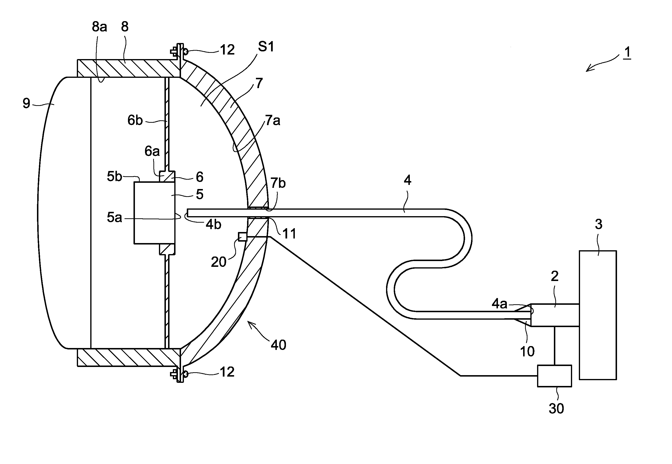
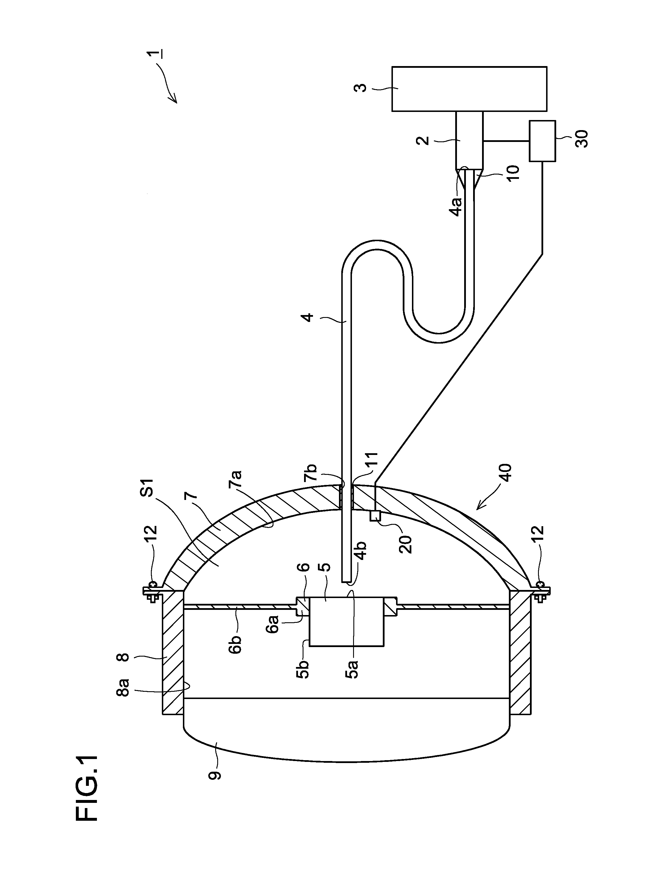
[0098]A description will be given of a structure of an illuminating device 1 of a first embodiment of the present invention with reference to FIG. 1.

[0099]The illuminating device 1 of the first embodiment of the present invention is one that is used as a headlamp that illuminates an area ahead of, for example, an automobile. As shown in FIG. 1, the illuminating device 1 includes an excitation light source 2 that emits laser light functioning as excitation light, a heat dissipation member 3 to which the excitation light source 2 is fixed, a light guide member 4 disposed anterior to the excitation light source 2, a fluorescent member 5 that is irradiated with laser light (the excitation light), a support member 6 that supports the fluorescent member 5, a reflection member 7 that reflects fluorescence, which is emitted from the fluorescent member 5, toward outside of a body 40 which will be described later, a bezel 8 that is fixed to a front edge of the reflection membe...

Example

Second Embodiment

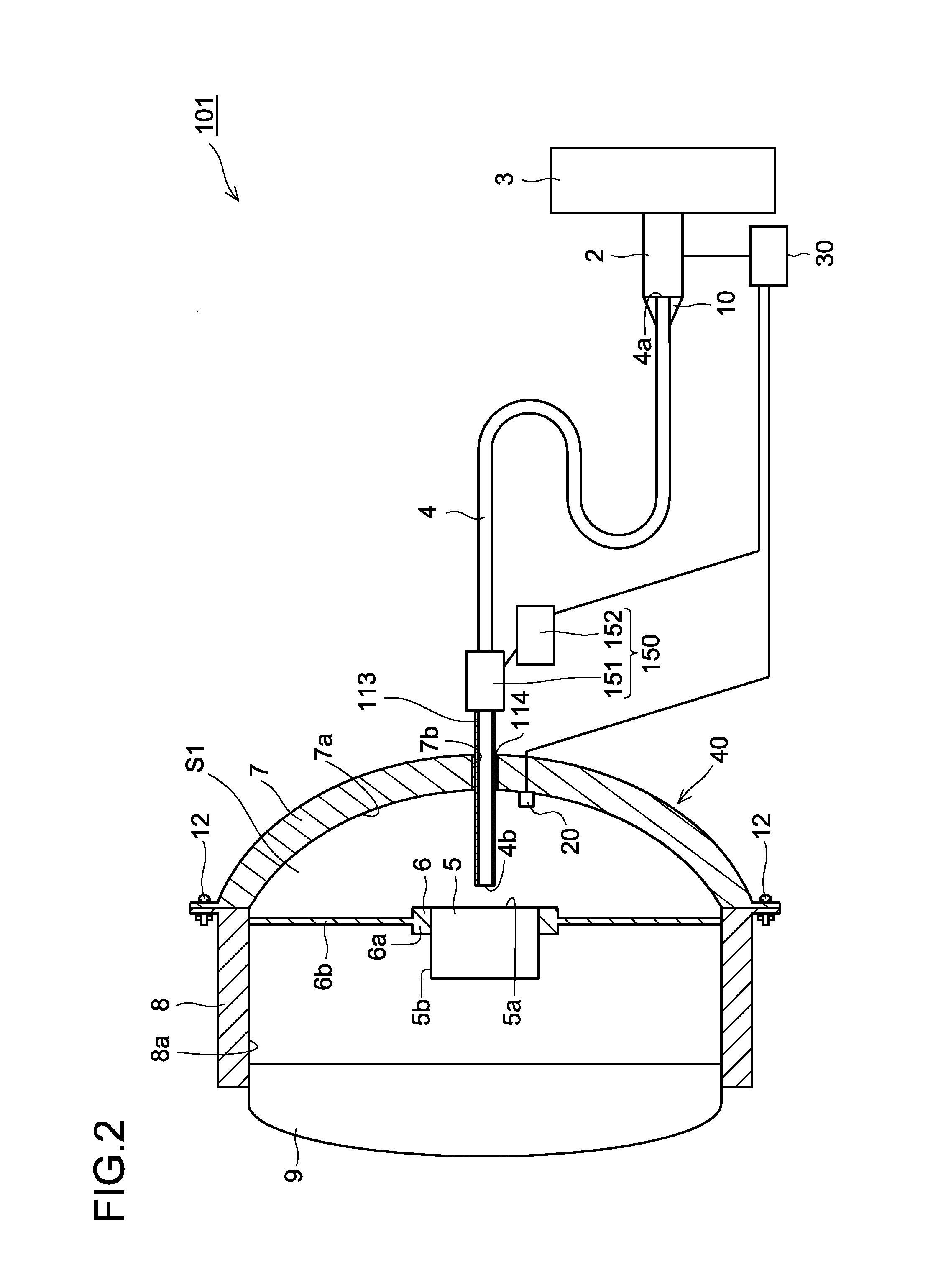
[0125]An illuminating device 101 of a second embodiment of the present invention includes, as shown in FIG. 2, a condensation removing unit 150 that removes condensation on a laser-light-passing surface. Note that the laser-light-passing surface means a surface through which laser light passes, and in the present embodiment, a laser-light-exit surface of an excitation light source 2, a laser-light-entrance surface 4a and a laser-light-exit surface 4b of a light guide member 4, and an irradiated surface 5a of a fluorescent member 5 are laser-light-passing surfaces. In the present embodiment, the condensation removing unit 150 removes condensation on the laser-light-exit surface 4b of the light guide member 4 among the laser-light-passing surfaces mentioned above.

[0126]The condensation removing unit 150 includes a heater 151 having a heating function, and a heater controller 152 that controls an operation of the heater 151.

[0127]Here, as shown in FIGS. 2 and 3, the li...

Example

Third Embodiment

[0140]As shown in FIG. 4, an illuminating device 201 of a third embodiment of the present invention includes a condensation removing unit 250 that includes a heater 251 having a heating function, and a heater controller 252 that controls an operation of the heater 251. In the present embodiment, the condensation removing unit 250 is configured such that it removes condensation on an irradiated surface 5a (a laser-light-passing surface) of a fluorescent member 5 (a member disposed in an optical path of laser light).

[0141]The heater 251 has a function of heating the fluorescent member 5. The heater 251 is thermally connected to fitting portions 6b of a support member 6, and heat generated by the heater 251 is transferred via the support member 6 to the fluorescent member 5.

[0142]The heater controller 252 is connected to the heater 251 and the controller 30, and configured similar to the heater controller 152 of the second embodiment.

[0143]In other respects, the structu...


PUM


Abstract

An illuminating device capable of improving eye-friendliness is provided. The illuminating device includes a fluorescent member that is irradiated with laser light functioning as excitation light to emit fluorescence, a condensation sensor that detects condensation near an optical path of the laser light, and a controller that limits irradiation of the laser light onto the fluorescent member in a case where the condensation sensor has detected condensation.

Description

[0001]This application is based on Japanese Patent Applications No. 2012-017772, No. 2012-017770, and No. 2012-017771 filed on Jan. 31, 2012, the contents of which are hereby incorporated by reference.BACKGROUND OF THE INVENTION[0002]1. Field of the Invention[0003]The present invention relates to an illuminating device, and in particular, the present invention relates to an illuminating device incorporating a fluorescent member that is irradiated with laser light functioning as excitation light.[0004]2. Description of Related Art[0005]There has conventionally been known an illuminating device provided with a fluorescent member to be irradiated with laser light functioning as excitation light. A known example of such an illuminating device is a vehicle headlamp (an illuminating device) provided with a semiconductor laser (an excitation light source) that emits laser light as excitation light, a fluorescent member that emits fluorescence on being irradiated with the laser light, a ref...

Claims


Application Information

Patent Timeline
IPC IPC(8): F21V9/16F21V8/00
CPCF21V9/16G02B6/0008F21S48/10F21V29/90F21S48/1145F21S48/1208F21S48/1241F21V23/0442F21S41/29F21S41/24F21S45/60F21S41/16F21S45/70F21V9/08F21V9/35F21V13/14F21S41/176
Inventor KISHIMOTO, KATSUHIKO
Owner SHARP KK
Why Eureka
Try Eureka