
Method and device for receiving multi-carrier optical signal

a multi-carrier optical and signal technology, applied in the field of communication, can solve the problems of high cost and high power consumption of multi-carrier optical signals in prior art, and achieve the effects of low cost, low power consumption and easy implementation

Active Publication Date: 2013-08-15
HUAWEI TECH CO LTD
View PDF21 Cites 8 Cited by
  • Summary
  • Abstract
  • Description
  • Claims
  • Application Information

AI Technical Summary

Benefits of technology

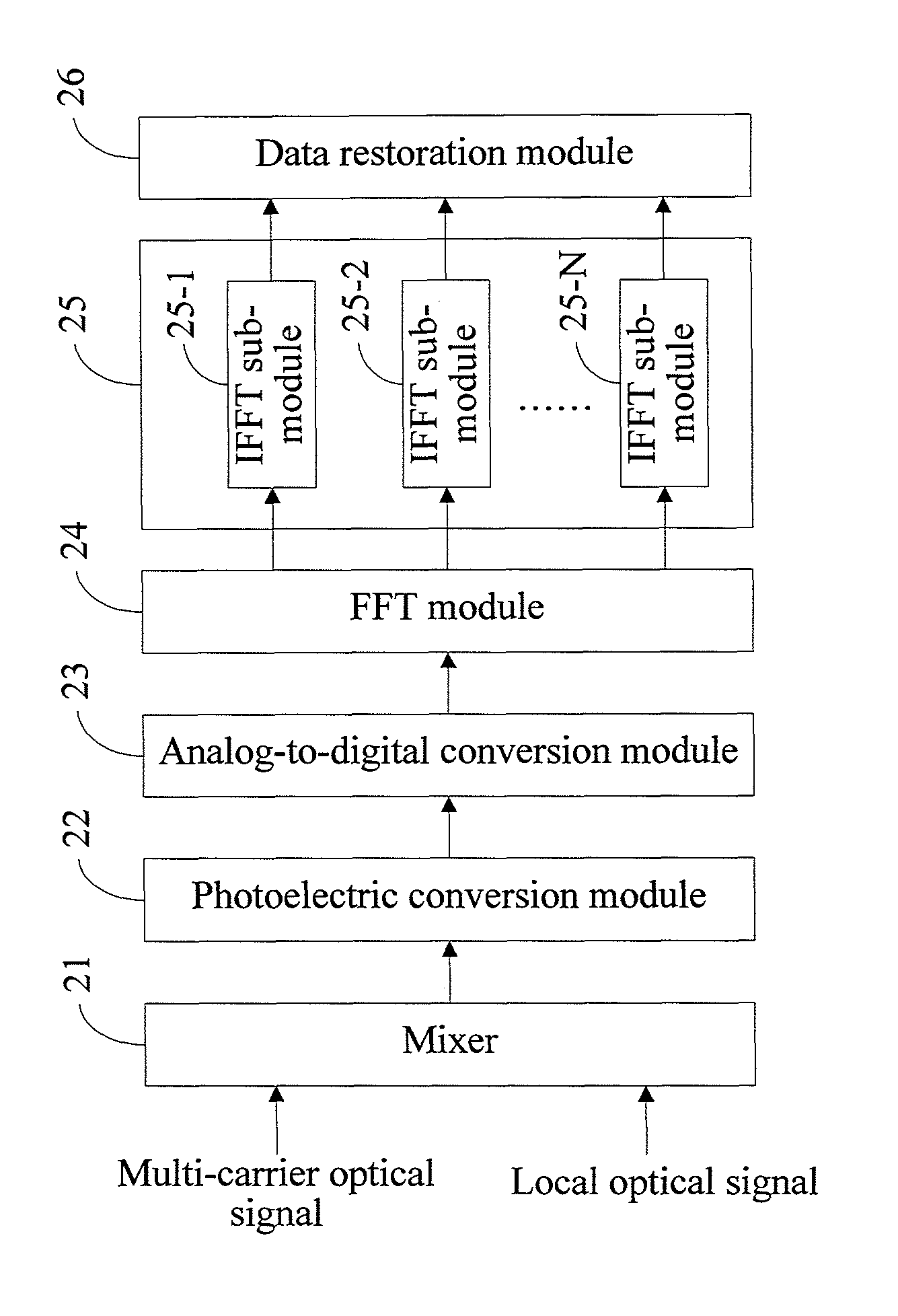
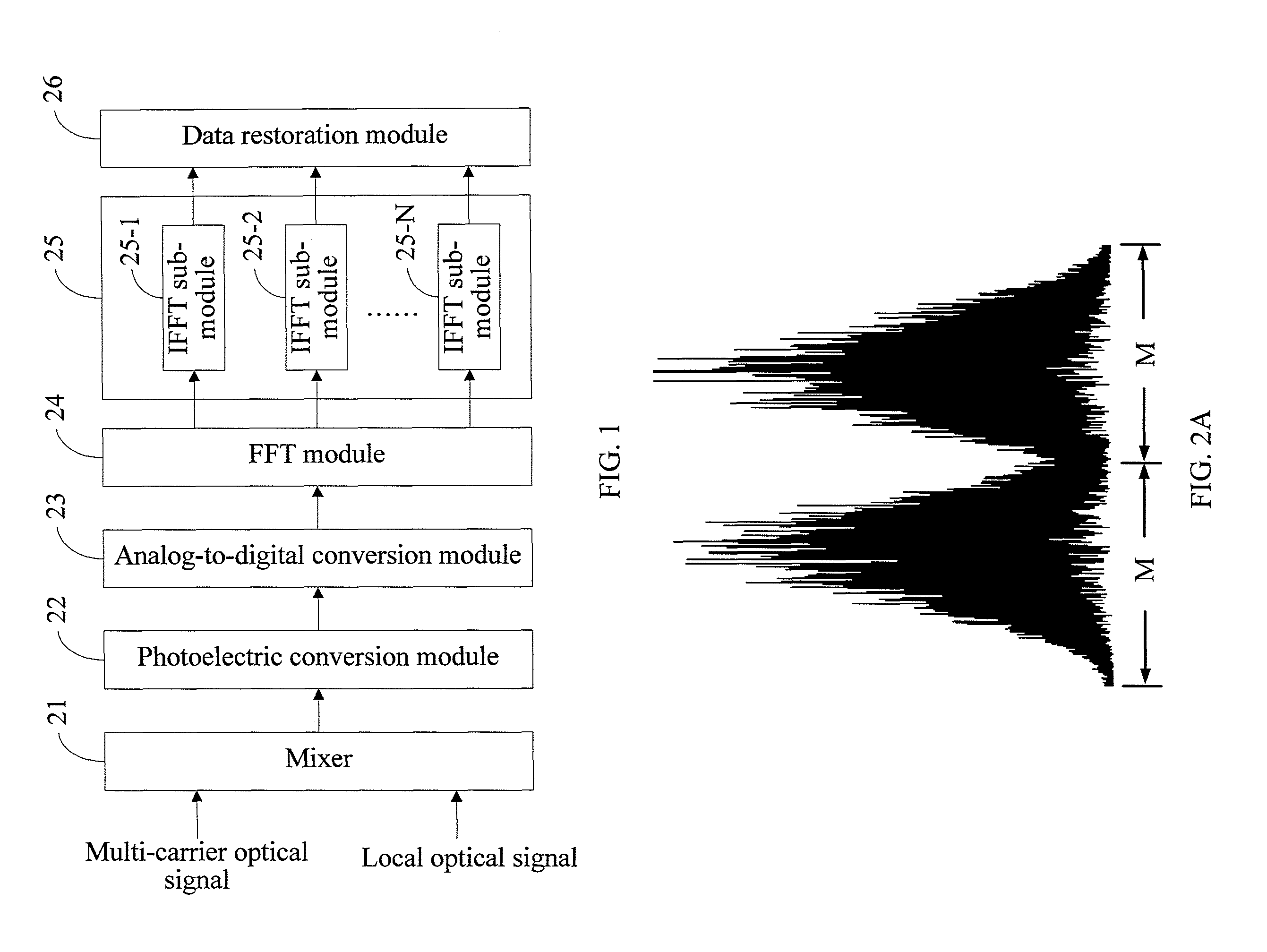
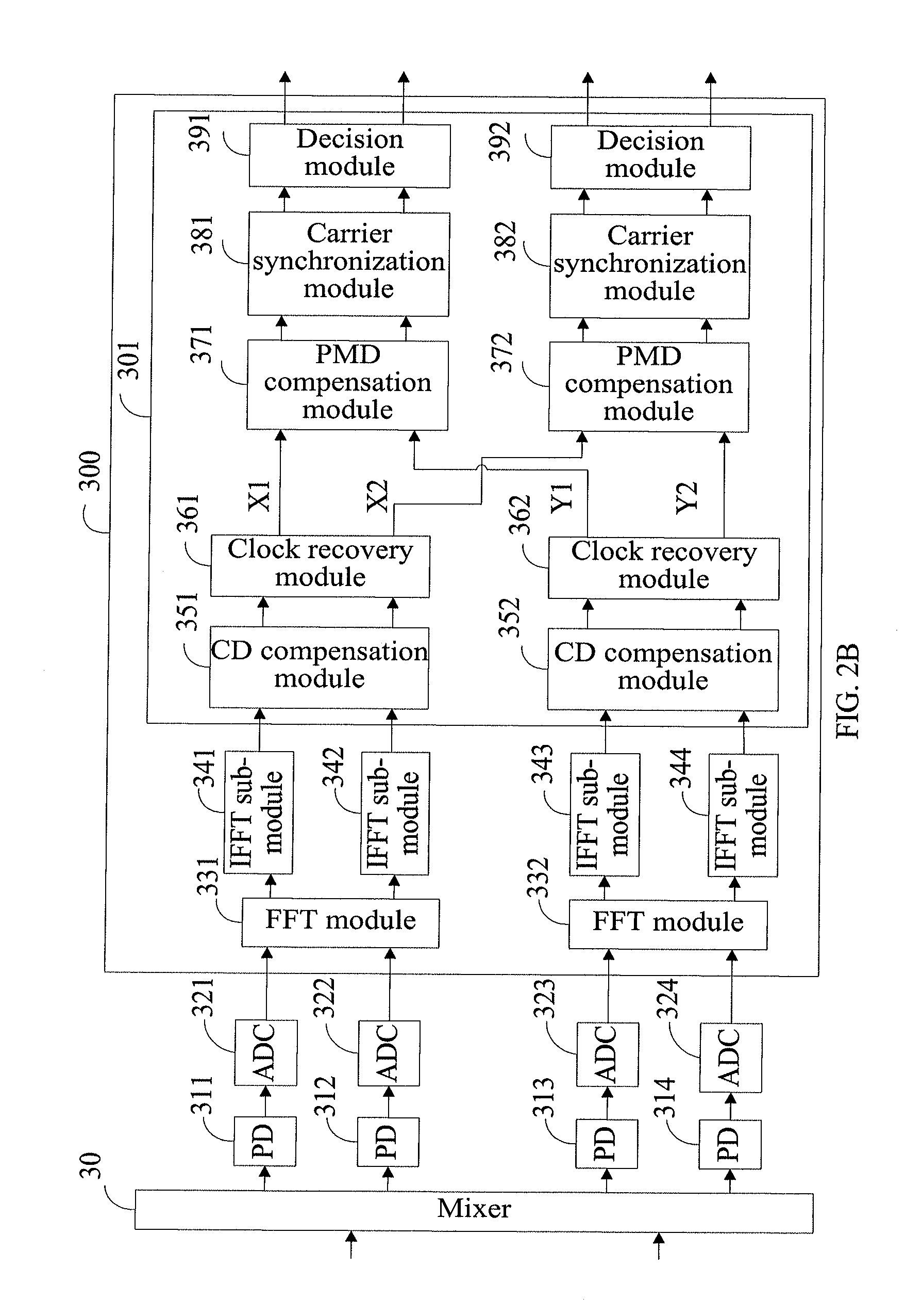
The present invention is a solution for receiving a multi-carrier optical signal that is cost-effective and power-efficient. The solution involves mixing the multi-carrier optical signal with a local optical signal, converting the mixed signal to the digital form, performing FFT processing, and finally restoring the data carried on each carrier based on its corresponding time domain signal. This solution requires only one set of coherent reception device, reducing complexity and facilitating sharing and exchange of channel information and parameters between carriers.

Problems solved by technology

It can be seen from the above that, both the solution for receiving a multi-carrier optical signal in the first piece of prior art and the solution for receiving a multi-carrier optical signal in the second piece of prior art require multiple independent sets of coherent reception devices, and therefore, the solutions for receiving a multi-carrier optical signal in prior art have problems of high cost and high power consumption.

Method used


Image

  • Method and device for receiving multi-carrier optical signal
  • Method and device for receiving multi-carrier optical signal
  • Method and device for receiving multi-carrier optical signal

Examples


Embodiment Construction

[0033]The technical solutions of embodiments of the present invention will be clearly and completely described in the following with reference to the accompanying drawings of the embodiments of the present invention. It is obvious that the embodiments to be described are only a part rather than all of the embodiments of the present invention. All other embodiments obtained by persons of ordinary skill in the art based on the embodiments of the present invention without creative efforts shall fall within the protection scope of the present invention.

[0034]In order to make the objectives, technical solutions and advantages of the present invention clearer, the embodiments of the present invention are described in detail in the following with reference to the accompanying drawings.

[0035]An embodiment of the present invention provides a device for receiving a multi-carrier optical signal, with its structure shown in FIG. 1. The device includes a mixer 21, a photoelectric conversion modu...


PUM


Abstract

The present invention relates to a method and a device. The method includes: mixing a multi-carrier optical signal with a local optical signal having the same center frequency as that of the multi-carrier optical signal; performing photoelectric conversion and analog-to-digital conversion on an optical signal obtained through the mixing to obtain a digital signal; performing FFT on the digital signal to obtain a frequency domain signal; grouping the frequency domain signal according to each frequency band corresponding to its respective carrier in the multi-carrier optical signal, and performing IFFT on each frequency domain signal group to obtain a corresponding time domain signal for each carrier; and performing data restoration on each time domain signal corresponding to its respective carrier to obtain data carried on each carrier. The solutions of the present invention only require one set of coherent reception device, and have low cost and low power consumption.

Description

CROSS-REFERENCE TO RELATED APPLICATIONS[0001]This application is a continuation of International Application No. PCT / CN2011 / 077609, filed on Jul. 26 2011, which is hereby incorporated by reference in its entirety.FIELD OF THE INVENTION[0002]The present invention relates to the field of communications, and in particular, to a method and a device for receiving a multi-carrier optical signal.BACKGROUND OF THE INVENTION[0003]At present, with the increasing transmission rate requirements, the baud rate of optical transmission systems continuously increases, which imposes increasingly higher rate requirements on components. To lower the rate requirements on components, multi-carrier modulation becomes a mainstream solution for optical communication systems. Currently, for multi-carrier modulation systems, a mode of independent and coherent reception of each carrier is commonly adopted in the industry. The independent and coherent reception of each carrier means that an independent set of ...

Claims


Application Information

Patent Timeline
Patent Type & Authority Applications(United States)
IPC IPC(8): H04B10/60
CPCH04B10/60H04B10/6161H04L27/2697H04L27/2657H04B10/6164
Inventor HUANG, YUANDALI, LIANGCHUANLIU, LINGLIU, LEI
Owner HUAWEI TECH CO LTD
Learn More