
Releasable two-part buckles

Inactive Publication Date: 2013-08-22
KINEMATIQ
View PDF9 Cites 2 Cited by
  • Summary
  • Abstract
  • Description
  • Claims
  • Application Information

AI Technical Summary

Benefits of technology

The present invention provides a two-part buckle that is strong in tension and has easy-to-flex arms. The buckle is designed to reduce the overall length as compared to prior art. The buckle also has a releasable feature that allows the user to easily disengage the hooks and arms. This reduces bending moments and allows for a more comfortable fit.

Problems solved by technology

Prior art buckles have a variety of disadvantages that emerge when the buckle needs to be small, strong and easy to use at the same time, especially when it has to be engaged / disengaged without visual feedback and when the user is wearing gloves.
Unfortunately, this increased releasing force makes it difficult for the user to engage / disengage the two buckle parts, especially without visual feedback and / or when the user is wearing gloves.
Simply stated, it has been determined by the present disclosure that the arms of the prior art buckles need to be stiff against bending to achieve high tensile strength of buckle, but increasing the bending-stiffness of the arms make the arms difficult to release.
This makes it hard for a user to find the hooks without visual feedback or when wearing gloves.

Method used


Image

  • Releasable two-part buckles
  • Releasable two-part buckles
  • Releasable two-part buckles

Examples


Embodiment Construction

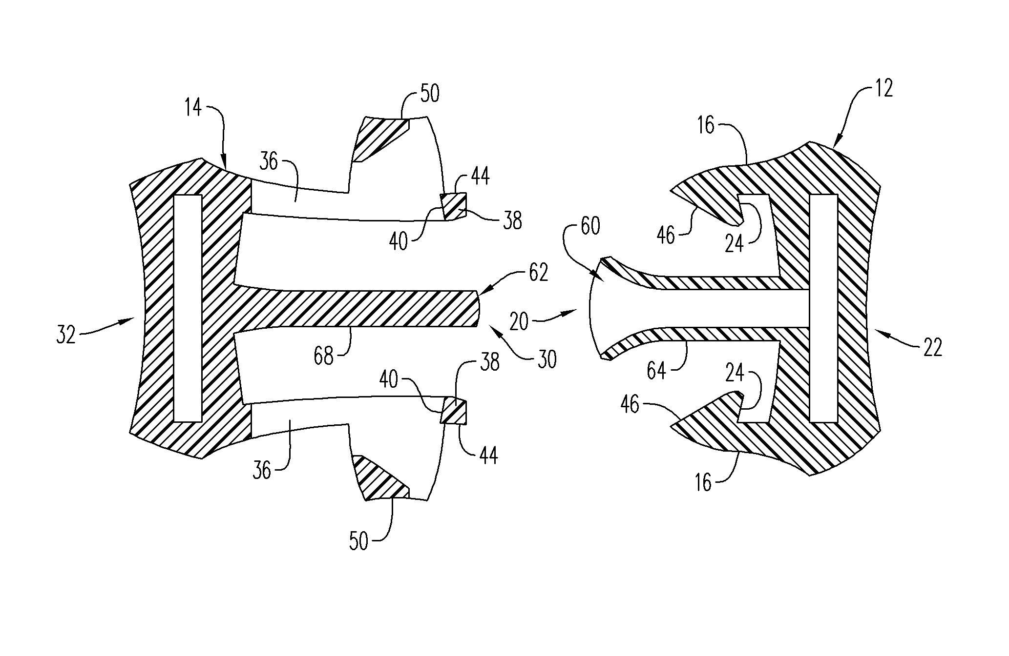
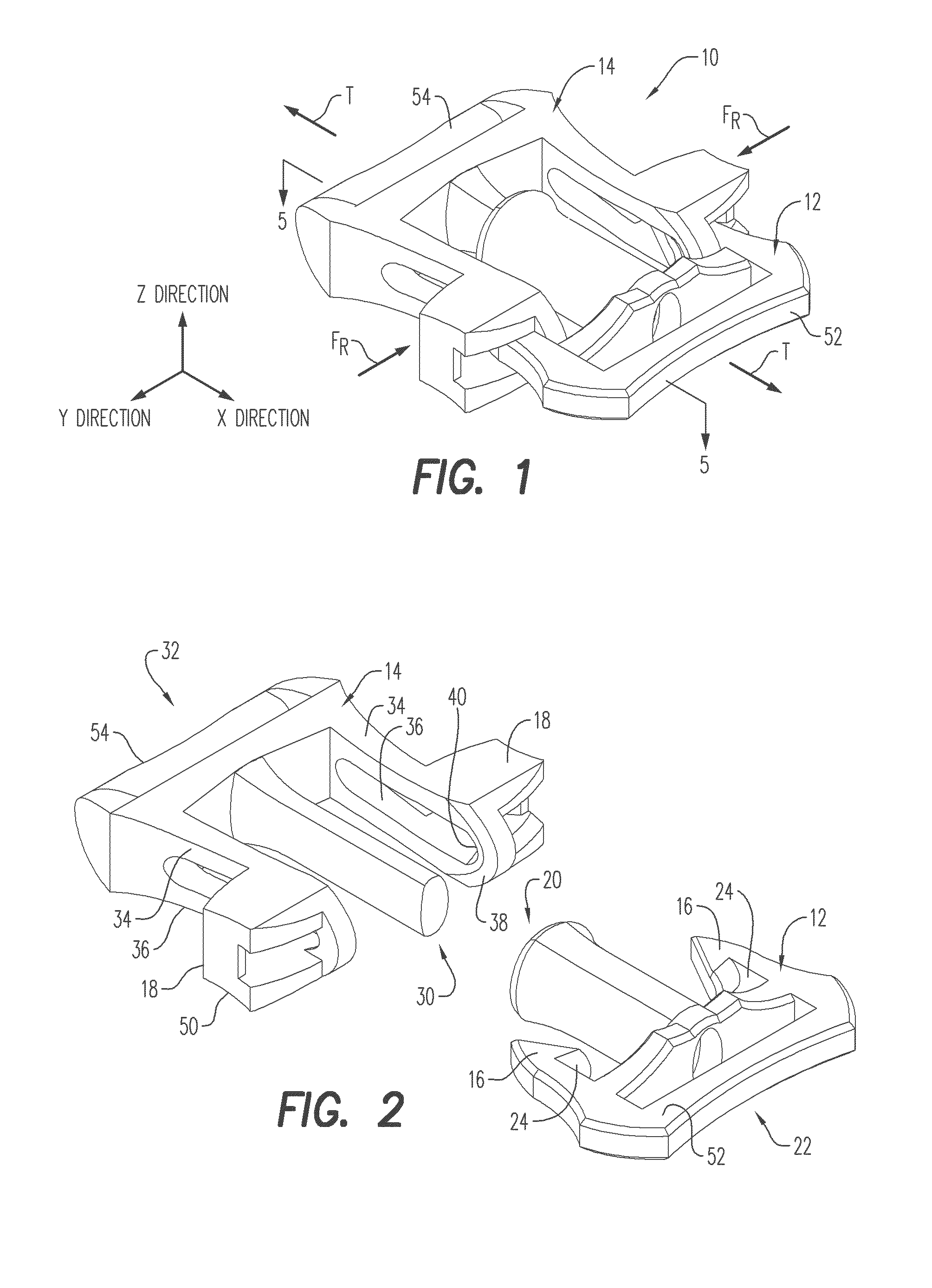
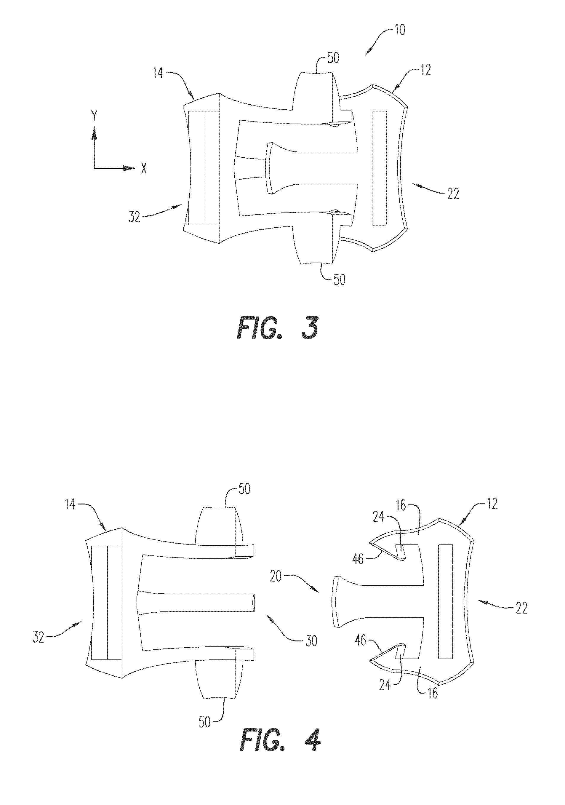
[0033]Referring to the drawings and in particular to FIGS. 1 and 2, an exemplary embodiment of a two-part buckle according to the present disclosure is shown and is generally referred to by reference numeral 10. Buckle 10 includes a first part 12 and a second part 14, which can be releasably engaged to one another.

[0034]Generally, first part 12 includes one or more stationary hooks 16 and second part 14 includes one or more arms 18. Arms 18 are resiliently movable between an engaged state (FIG. 1) where the arms are engaged with hooks 16, and a disengaged state (FIG. 2) where the arms and hooks are disengaged from one another.

[0035]Advantageously, buckle 10 is configured so that first and second parts 12, 14 can easily be engaged and disengaged from one another when desired, while mitigating instances of the parts being inadvertently disengaged one another when placed in tension, which is illustrated by arrows (T) of FIG. 1.

[0036]Without wishing to be bound by any particular theory,...


PUM


Abstract

A releasable two-part buckle having a first part and a second part is provided. The first and second parts have forward and rearward ends. A hook extends towards the forward end of the first part, while an arm extends towards the forward end of the second part. The hook has a first engagement surface. The arm has a center axis and a loop with a second engagement surface. The arm moves between an engaged state having the engagement surfaces engaged at a contact surface and a disengaged state having the engagement surfaces disengaged. In some embodiments, the buckle is configured so that the contact surface bisects the center axis in the engaged state. In other embodiments, the buckle is configured so that, when in the engaged state, a tension applied to the buckle induces substantially no bending moment in the arm towards the disengaged state.

Description

BACKGROUND OF THE INVENTION[0001]1. Field of the Invention[0002]The present disclosure is related to releasable two-part buckles. More particularly, the present disclosure is related to releasable two-part buckles that can easily be engaged and disengaged, yet are resistant to inadvertent disengagement.[0003]2. Description of Related Art[0004]Common two-part buckles are well known for connecting the end of a flexible strap to another flexible strap or to a mating part on another object. Various approaches have been used to effect the engagement and disengagement of such buckles.[0005]An approach frequently used in buckles for commercial applications makes use of plastic molded first and second parts which are fastened to two strap ends desired to be coupled together. The first part snap-engages into a socket defined within the second part. Specifically, the first part has a pair of longitudinal resilient arms, each of them provided with a hook, which lock the buckle by cooperating w...

Claims


Application Information

Patent Timeline
IPC IPC(8): A44B11/26
CPCY10T24/45534A44B11/263
Inventor KOENIG, LEONARD MANFRED
Owner KINEMATIQ
Learn More