Method and control circuit for starting a gas-discharge lamp

Active Publication Date: 2013-08-22
AUTOMOTIVE LIGHTING REUTLINGEN GMBH
View PDF5 Cites 3 Cited by
  • Summary
  • Abstract
  • Description
  • Claims
  • Application Information

AI Technical Summary

Benefits of technology

[0022]The result is the advantage that a largest possible portion of the energy stored in the booster capacitor is available for the acquisition (i.e., energy is available For the releasing of a snowballing breakdown and generation of a stable electric arc between the electrodes of the gas-discharge lamp). In other words, by the invention, a larger portion of

Problems solved by technology

As a result, the current flow through the lamp when

Method used


Image

  • Method and control circuit for starting a gas-discharge lamp
  • Method and control circuit for starting a gas-discharge lamp
  • Method and control circuit for starting a gas-discharge lamp

Examples


Embodiment Construction

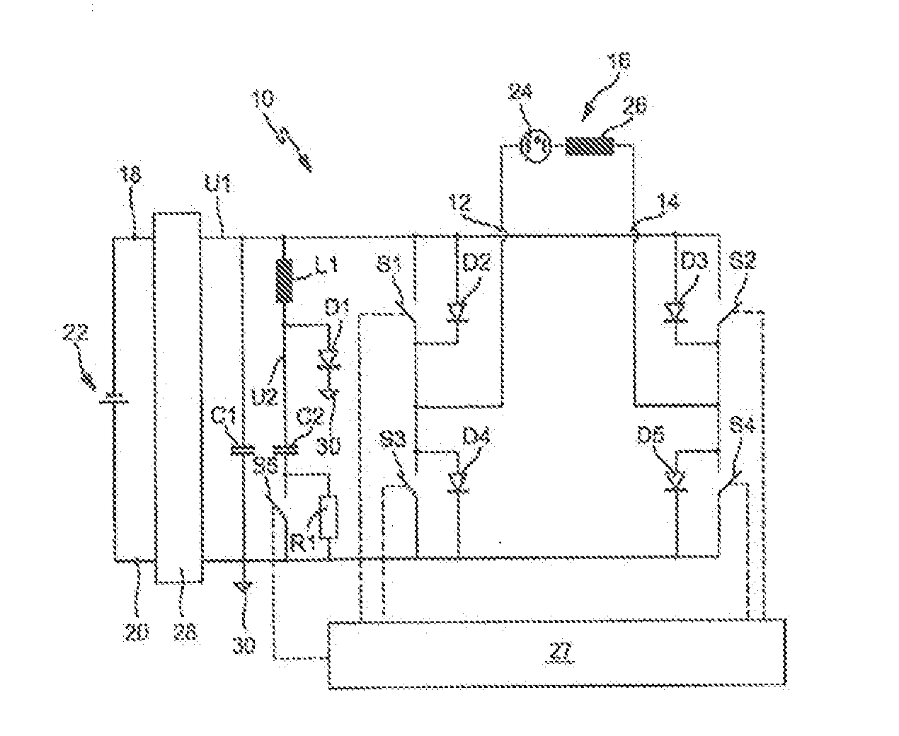
[0031]In detail, FIG. 1 shows a control circuit 10 connected by circuit points 12, 14 to a gas-discharge lamp 16 and circuit points 18, 20 to an electric-power source 22. The gas-discharge lamp 16 is designed for a motor-vehicle lighting device—in particular, a lamp of the type D1, D3, or D5 having an integrated ignition device. The invention can, however, also be used with lamps of the type D2, D4, or D6 having external ignition devices. The electric-power source 22 is a power or current source in the electric wiring system of the motor vehicle (e.g., a motor-vehicle battery).

[0032]In the embodiment, the gas-discharge lamp 16 has a lamp 24 (i.e., glass bulb filled with gas) having two electrodes and an integrated ignition device of which FIG. 1 shows a secondary inductor 26 of an ignition transformer. The secondary inductor 26 is connected in series in the current path between the circuit points 12, 14 and equipped to generate an ignition-voltage impulse of numerous kilovolts—in pa...


PUM


Abstract

A method operates a gas-discharge lamp (16) in a transition from a “deactivated” state without an electric arc to a stable “light-generating” state. The method comprises steps of discharging a booster capacitor (C2) in an “acquisition” phase following an ignition-voltage impulse via a current path that conducts a current flowing through the gas-discharge lamp (16) and in which an inductor (L1) having at least one switch (S5) lies in series and cyclically discharging the booster capacitor (C2) by a repeated alternating closing and opening of the switch (S5).

Description

CROSS-REFERENCE TO RELATED APPLICATIONS[0001]This is a “national stage” application of International Patent Application PCT / EP2011 / 055831 filed on Apr. 13, 2011, which, in turn, claims priority to and benefit of the filing date of German Patent Application 10 2010 018 325.3 filed on Apr. 27, 2010.BACKGROUND OF INVENTION [0002]1. Field of Invention[0003]The invention relates to a method and control circuit for, in general, starting a gas-discharge lamp and, in particular, operating the lamp in a transition from a “deactivated” state without an electric arc to a stable “light-generating” state.[0004]2. Description of Related Art[0005]A method for operating a gas-discharge lamp in a transition from a “deactivated” state without an electric arc to a stable “light-generating” state and a corresponding control circuit are known per se. With the operation of a gas-discharge lamp—in particular, one to be used in gas-discharge lamps of lighting apparatuses designed for motor vehicles used on...

Claims


Application Information

Patent Timeline
IPC IPC(8): H05B41/04
CPCH05B41/2881H05B41/04H05B41/388Y02B20/00
Inventor KLUETZ, PETERLAUBENSTEIN, RUEDIGERJOHANN, CHRISTIANMOOSMANN, BJOERNHERRMANN, MICHAELRODER, MATTHIAS
Owner AUTOMOTIVE LIGHTING REUTLINGEN GMBH
Why Eureka
Try Eureka