Cavity Receivers for Parabolic Solar Troughs

a parabolic solar and receiver technology, applied in the field of concentrated solar power, can solve the problems of increasing temperature and cost, and reducing the cost of storage, so as to reduce the levelized cost of energy and be less costly

Active Publication Date: 2013-08-29
NORWICH TECH
View PDF20 Cites 17 Cited by
  • Summary
  • Abstract
  • Description
  • Claims
  • Application Information

AI Technical Summary

Benefits of technology

The invention provides improved receivers for concentrating solar power that overcome issues with current receivers such as vacuum degradation and high costs. The receivers are durable, operate at high temperatures, and can be used in both new power plants and existing power plants. They require less thermal storage media and have reduced energy requirements for storage compared to current receivers. The receivers also have improved optical and thermal efficiency. The invention also includes a cover for the receiver that prevents energy loss and a shaping of the receiver that minimizes wind resistance. Overall, the invention provides a more cost-effective and efficient solution for concentrating solar power.

Problems solved by technology

Moreover, for most thermal energy storage systems, the operational temperature range has an effect on the cost of storage: that is, increased temperature tends to decrease cost.

Method used


Image

  • Cavity Receivers for Parabolic Solar Troughs
  • Cavity Receivers for Parabolic Solar Troughs
  • Cavity Receivers for Parabolic Solar Troughs

Examples


Embodiment Construction

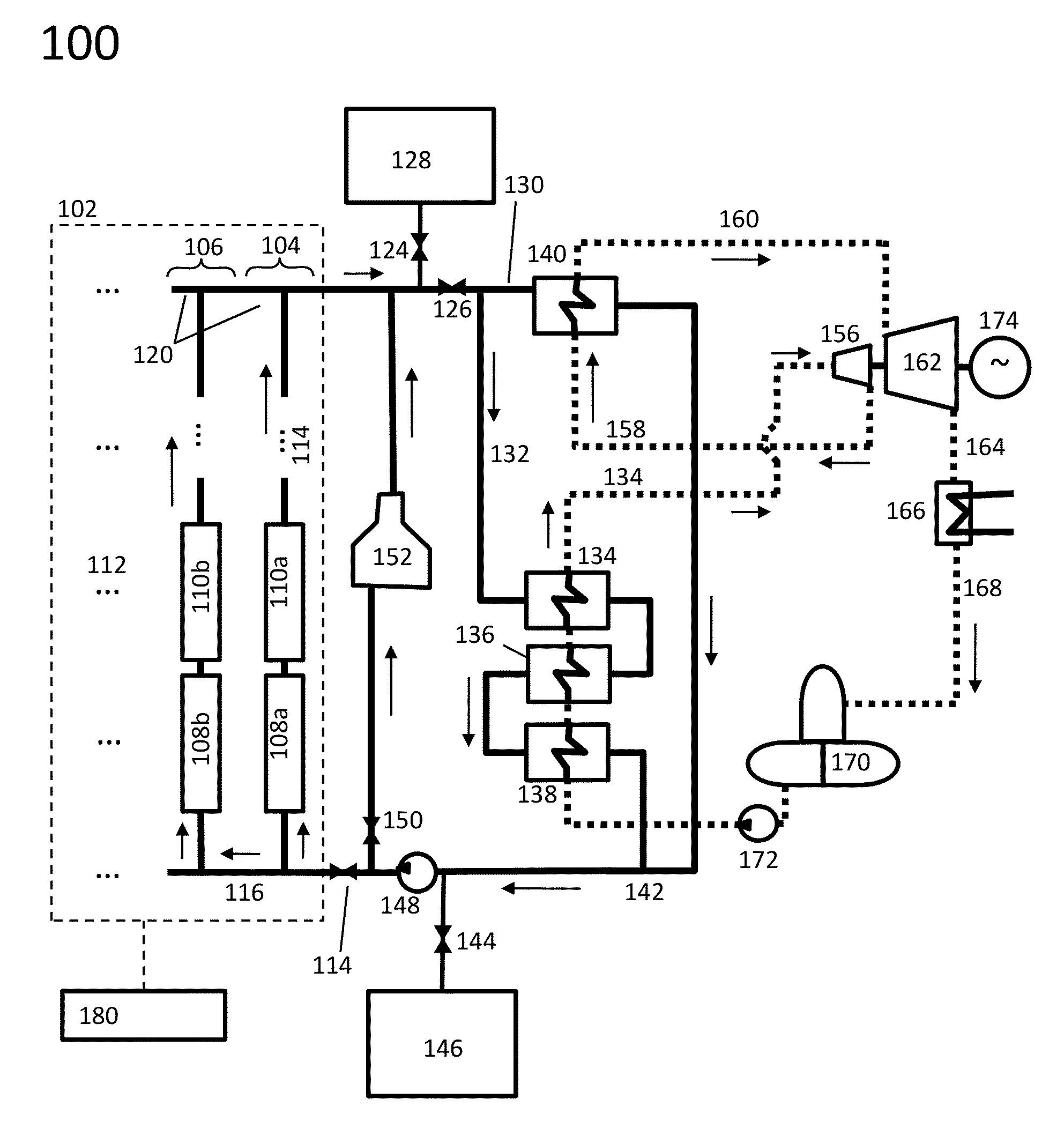
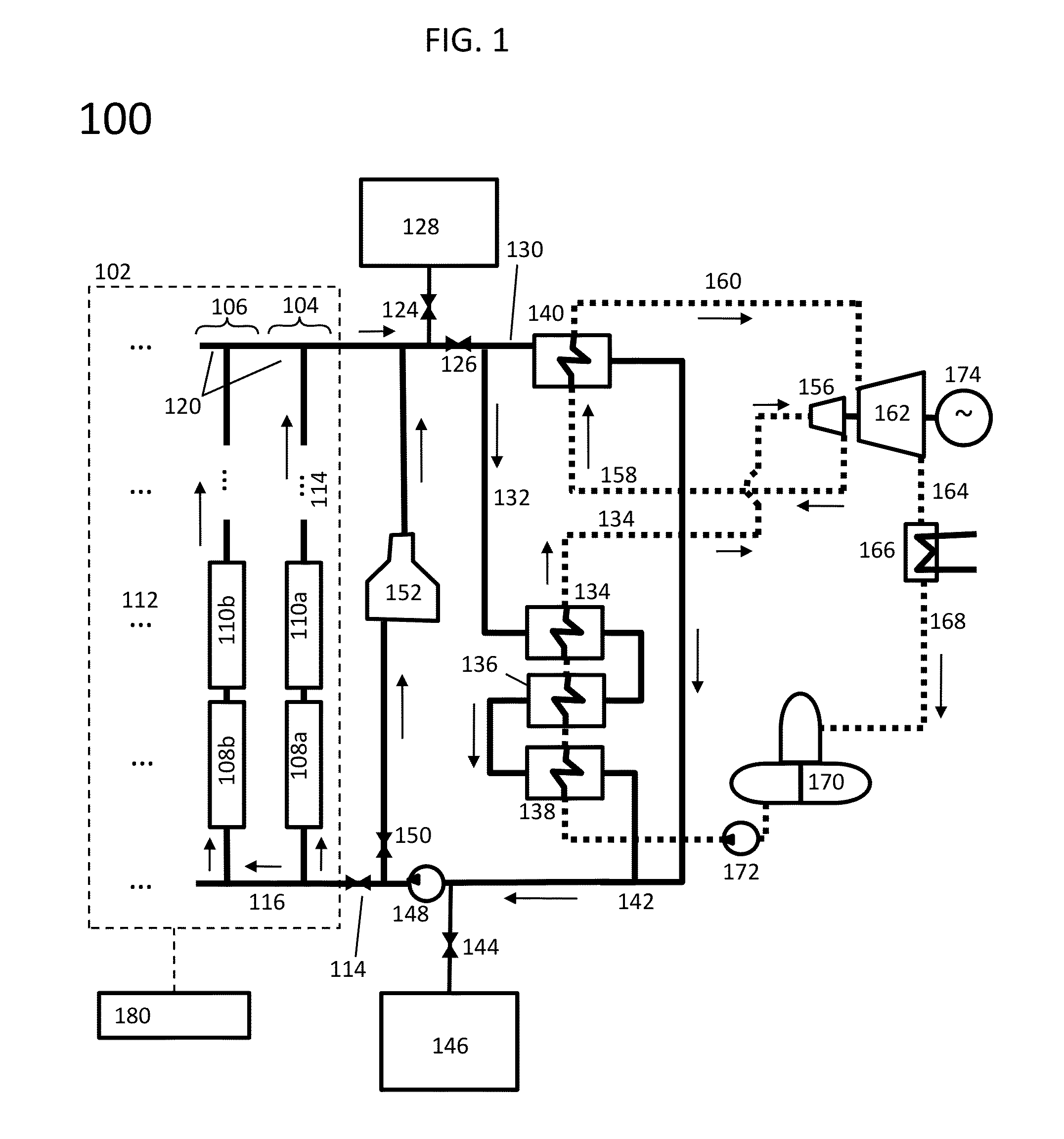
[0114]FIG. 1 depicts an illustrative system 100 for the collection of solar energy in the form of heat and the conversion of the collected heat to electricity. Subsequent figures will clarify the application of embodiments of the invention to such a system and similar systems which use the collected heat in other manners, such as to generate steam for industrial processes. The system 100 depicted in FIG. 1 comprises a solar field 102 for the collection of solar energy. The solar field 102 comprises a plurality N rows (e.g., row 104, row 106), depicted in FIG. 1 as viewed from above, where each row comprises a plurality M receivers (e.g., receivers 108a, 108b; receivers 110a, 110b, etc.) upon which solar radiation is focused by parabolic collectors (not depicted). The plurality of the N rows is indicated in FIG. 1 by horizontal ellipses (e.g., ellipsis 112); the plurality of M receivers in each of the N rows is indicated in FIG. 1 by vertical ellipses (e.g., ellipsis 114). The number...


PUM


Abstract

A tubular heat-absorbing element partly enclosed in an insulating layer or jacket, has absorbing surface that is accessible to solar radiation. The thermal insulation is designed to provide entry to solar radiation by way of a cavity. The absorbing surface can be substantially planar.

Description

CROSS-REFERENCE TO RELATED APPLICATIONS[0001]This application claims priority to and the benefit of co-pending U.S. provisional patent application Ser. No. 61 / 583,585, filed Jan. 5, 2012, which application is incorporated herein by reference in its entirety.STATEMENT REGARDING FEDERALLY FUNDED RESEARCH OR DEVELOPMENT[0002]This invention was made with government support under DE-EE0005803 awarded by the DOE. The government has certain rights in the invention.FIELD OF THE INVENTION[0003]The invention relates to concentrating solar power in general and particularly to a system that employs reflective troughs to focus solar radiation upon a linear receiver.BACKGROUND OF THE INVENTION[0004]Solar parabolic troughs, which focus sunlight on tubes carrying a fluid that conveys heat for steam generation (e.g. to a steam-driven electric generator, or for industrial process heat) or to a body of material for energy storage, are a proven, reliable, and relatively low-cost technology for collecti...

Claims


Application Information

Patent Timeline
Patent Type & Authority Applications(United States)
IPC IPC(8): F24J2/05F24J2/24F24S10/40F24S10/70F24S10/75F24S20/20F24S23/30F24S23/70F24S23/71F24S23/74F24S90/00
CPCF24J2/055Y02E10/45F03G6/06F24J2/54F24J2/26F24J2/05F24J2/12F24J2/0488F24J2/07F24J2/08F24J2/1047F24J2/14F24J2/4609F24J2/485F24J2/50F24J2/541F24J2002/508Y02E10/44Y02E10/46Y02E10/41F24J2/24F24S80/50F24S10/45F24S20/20F24S23/30F24S23/80F24S23/74F24S40/10F24S70/16F24S30/425F24S80/56F24S70/225Y02E10/47F24S70/60F24S10/40F24S10/70F24S10/75F24S30/40Y02E10/40F03G6/061
Inventor STETTENHEIM, JOELMCBRIDE, TROY O.BRAMBLES, OLIVER J.
Owner NORWICH TECH
Why Eureka
Try Eureka