Oscillating rotary electric power tool

Active Publication Date: 2013-08-29
MAKITA CORP
View PDF2 Cites 7 Cited by
  • Summary
  • Abstract
  • Description
  • Claims
  • Application Information

AI Technical Summary

Benefits of technology

[0014]According to the oscillating rotary electric power tool according to the first aspect of the invention, the elastic body elastically deforms between the coupling member and the crankshaft in the direction of the identical axis to that of the output shaft of the motor so that the elastic body can adhere to the coupling member and the crankshaft. Therefore, as a result of increasing the resistance by the elastic body in the rotational direction of the coupling member or the rotational direction of the crankshaft, the unity between the coupling member and the crankshaft in the rotational direction is increased. Thus, it is possible to prevent the generation of abnormal noise caused by hitting of the coupling member and the crankshaft.
[0015]In addition, the elastic body just deforms elastically to adhere to the coupling member and the crankshaft, and no force to squash the elastic body is applied to the elastic body in the rotational direction during the rotation of the coupling member or the rotation of the crankshaft. Since the elastic body is not squashed and torn off, the durability of the elastic body can be improved.
[0016]According to the second aspect of t

Problems solved by technology

In such a case, since the elastic body can be torn off by this force, i

Method used


Image

  • Oscillating rotary electric power tool
  • Oscillating rotary electric power tool
  • Oscillating rotary electric power tool

Examples


Example

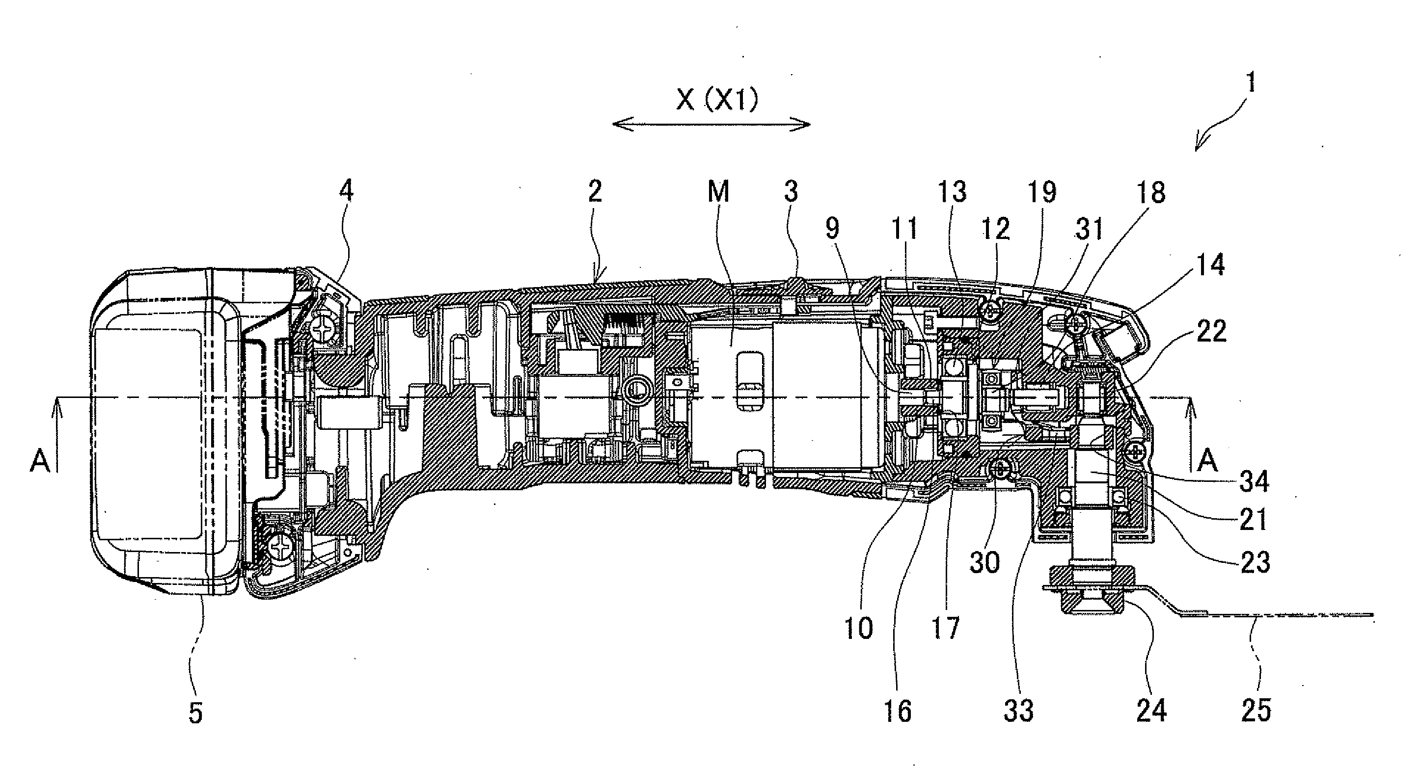
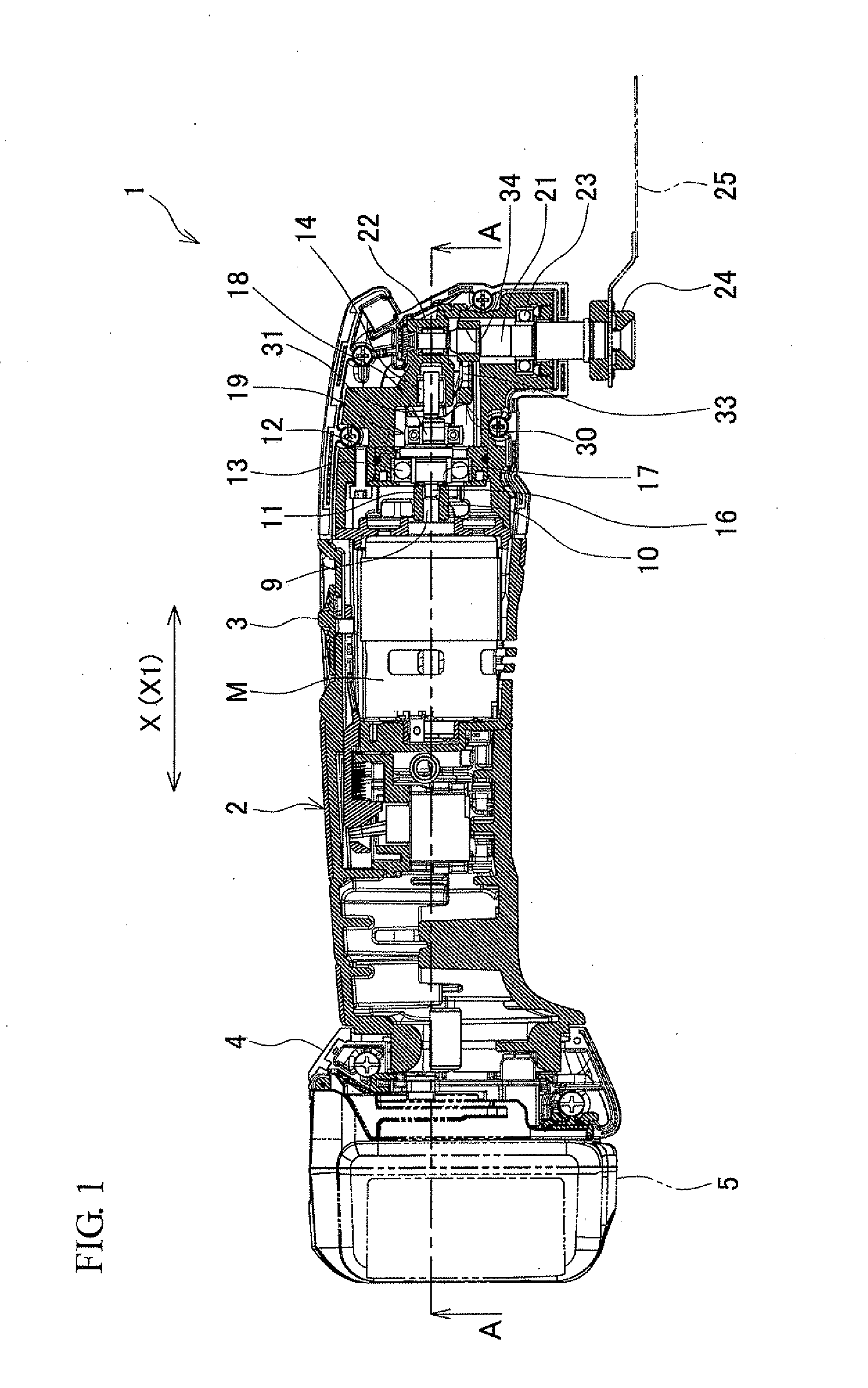
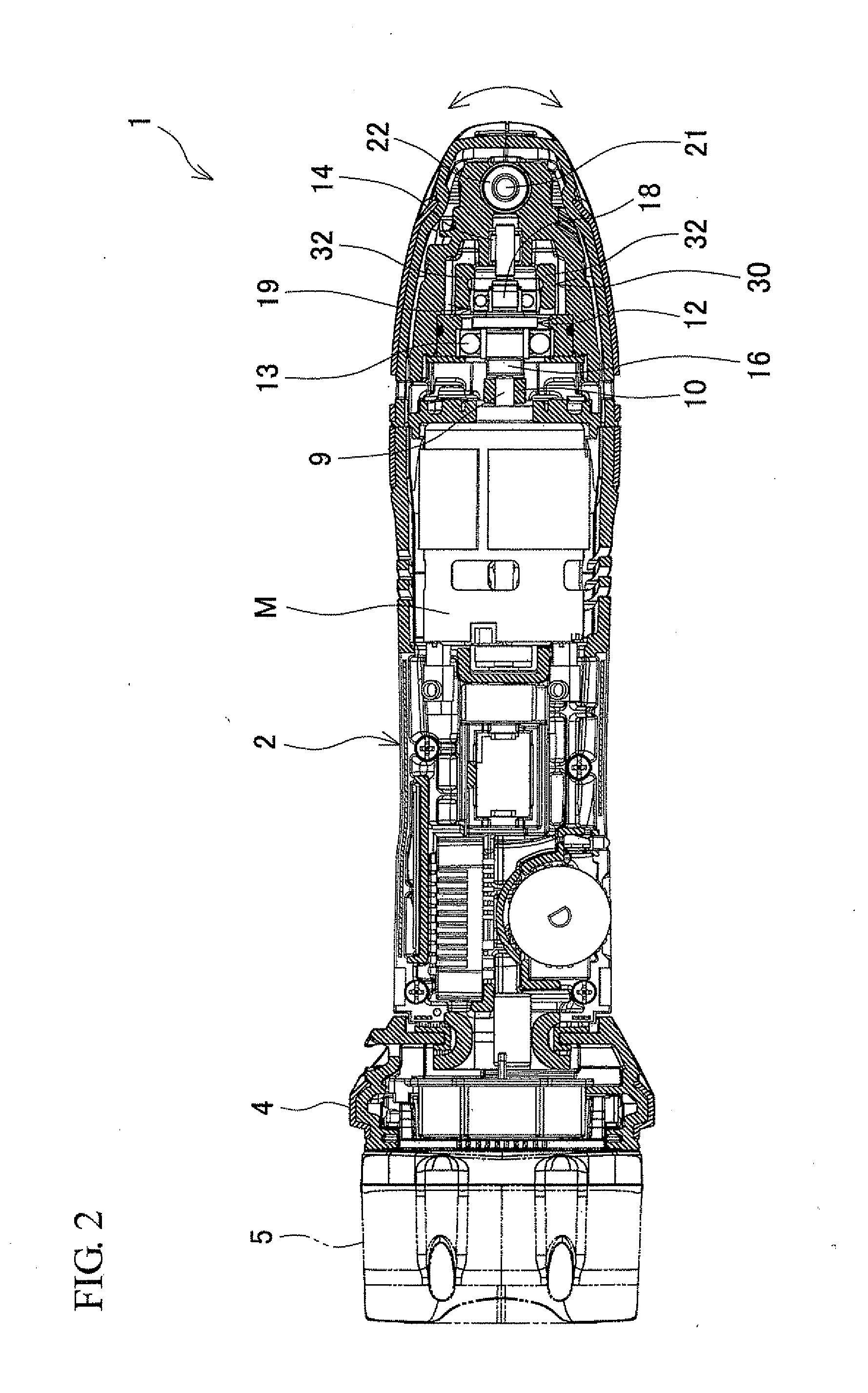
[0023]An embodiment of the present invention will be described with reference to FIG. 1 to FIG. 3. An oscillating rotary electric power tool 1 shown in FIG. 1 and FIG. 2 includes a housing 2, which is molded with resin, has a round cross-section, and extends in the longitudinal direction (horizontal direction in FIG. 1 and FIG. 2) of the oscillating rotary electric power tool 1. A motor M is accommodated inside the housing 2, and a slide lever 3 (see FIG. 1) is provided on the outer circumference of the housing 2 to switch the motor M between an on-state and an off-state. Further, a battery attachment portion 4 is provided in a rear end portion of the housing 2 (left side of FIG. 1 and FIG. 2). A battery pack 5 is removably attached to the battery attachment portion 4 to feed power to the motor M when the slide lever 3 is switched to the on-state.

[0024]As shown in FIG. 1 and FIG. 2, a cylindrical coupling member 10 is concentrically coupled to an output shaft 9 in front of the outpu...


PUM


Abstract

An oscillating rotary electric power tool, in which a spindle with a distal end tool attached thereto is projected downward from a front end portion of a housing accommodating a motor, and the housing also accommodates a coupling member rotatable integrally with an output shaft of the motor, a crankshaft fitted with the coupling member in a depression and projection fitting structure, and a link member to which the spindle is fixed and power is transmitted from the crankshaft to rotate clockwise and counterclockwise in an oscillating manner so that the link member will be driven by the motor to rotate the spindle clockwise and counterclockwise in the oscillating manner, wherein an elastic body is interposed between the coupling member and the crankshaft in the same axial direction as the output shaft.

Description

BACKGROUND OF THE INVENTION[0001]This application claims the benefit of Japanese Patent Application Number 2012-038864 filed on Feb. 24, 2012, the entirety of which is incorporated by reference.[0002]1. Technical Field[0003]This invention relates to an oscillating rotary electric power tool in which a spindle with a distal end tool attached thereto is projected downward from a front end portion of a housing accommodating a motor so that the spindle will be driven by the motor to rotate clockwise and counterclockwise in an oscillating manner.[0004]2. Background Art[0005]As shown in FIG. 4, there is known a conventional oscillating rotary electric power tool 50, where a motor M is accommodated in a housing 51 extending in a longitudinal direction (horizontal direction of FIG. 4) of the oscillating rotary electric power tool 50, and a spindle 53 to which various kinds of distal end tools 52 are able to be attached is projected downward from a front end portion (right side in FIG. 4) of...

Claims


Application Information

Patent Timeline
IPC IPC(8): B25F5/00
CPCB25F5/00B25F5/006B24B47/16B24B23/04B25D17/11F16D3/68F16D3/76
Inventor ITAKURA, TORUNAKAMURA, SHINTAHARA, TAKAYUKIMIZUTANI, AKIRA
Owner MAKITA CORP
Why Eureka
Try Eureka