Inkjet print calibration using test patches and densitometer

a technology of densitometer and test patch, which is applied in the field ofinkjet printing system, can solve the problems of adversely affecting the quality of printed digital image, adversely affecting the quality and consistency of printed image,

Inactive Publication Date: 2013-08-29
CARESTREAM HEALTH INC
View PDF2 Cites 25 Cited by
  • Summary
  • Abstract
  • Description
  • Claims
  • Application Information

AI Technical Summary

Benefits of technology

[0006]An object of the present invention is to provide an inkjet printing system employing test patches and a densitometer to calibrate an inkjet printhead to compensate for dynamic factors adversely affecting the quality of a printed digital image.
[0017]By printing with an inkjet printhead and measuring with a transmissive densitometer the density of one or more series of test patches on a sheet of transparent film, and making adjustments to pixel values of output pixels to be printed by an inkjet printer based on differences between the measured density values and expected density values of the series of test patches, the inkjet printing system and inkjet printing system calibration methods described herein can dynamically compensate for a plurality of factors that would otherwise adversely impact the quality of the printed image on the transparent film.

Problems solved by technology

While inkjet printing systems are widely employed in many applications, including medical applications where printing is done on film, the quality of the printed digital image can be adversely impacted by many factors such as the type of ink, the age of the ink, the type of film (e.g. opaque and transparent), the age of the film (e.g. the same film can exhibit different imaging properties as it ages), the film lot (e.g. the same type of film from different production lots can exhibit different properties), environmental conditions (e.g. temperature and humidity), and the volume of ink employed (e.g. larger volumes of carrier fluids are removed over a longer period of time when larger volumes of ink are used).
Such factors can constantly vary and adversely impact the quality and consistency of the printed image.

Method used


Image

  • Inkjet print calibration using test patches and densitometer
  • Inkjet print calibration using test patches and densitometer
  • Inkjet print calibration using test patches and densitometer

Examples


Embodiment Construction

[0024]The following is a detailed description of the preferred embodiments of the invention, reference being made to the drawings in which the same reference numerals identify the same elements of structure in each of the several figures.

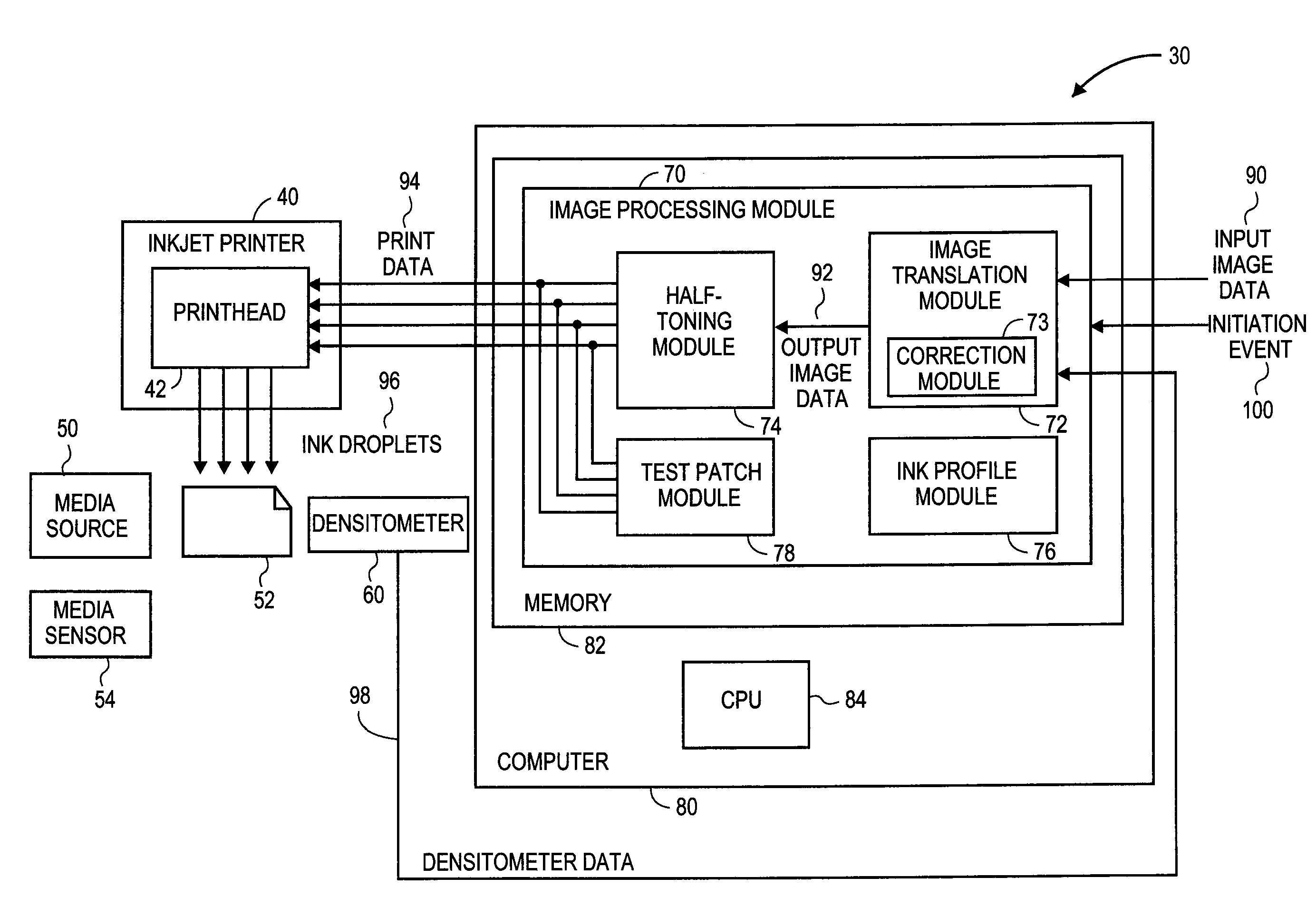
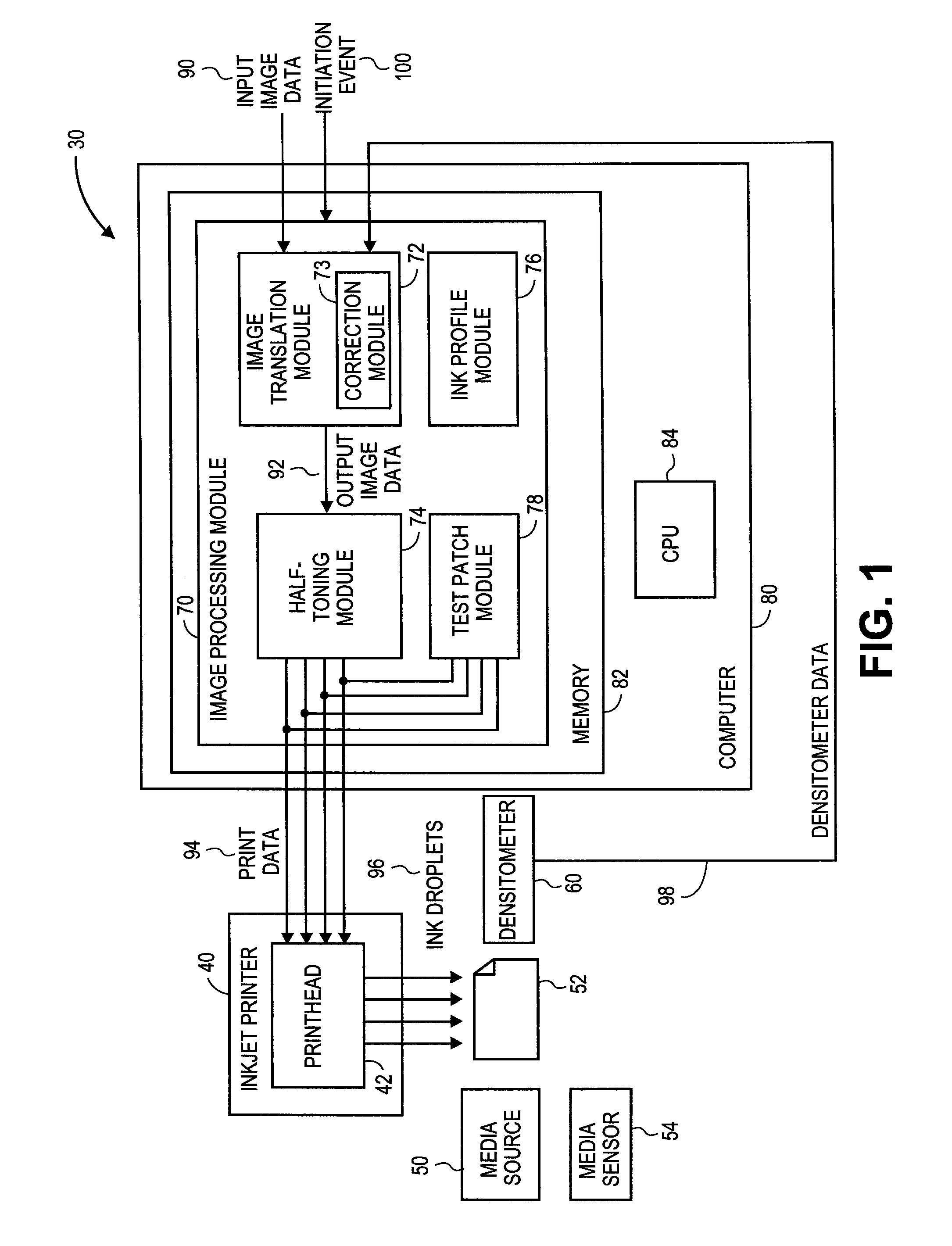
[0025]FIG. 1 is a block and schematic diagram generally illustrating an example of an inkjet printing system 30 configured to print test patches and employing a densitometer to measure a density of said test patches in order to adjust the fashion in which ink droplets are ejected from a printhead to compensate for factors that would otherwise compromise image quality according to embodiments of the present application as described herein.

[0026]According to the embodiment of FIG. 1, inkjet printing system 30 includes an inkjet printer 40 having a printhead 42, a media source 50 providing sheets of imaging media 52, a densitometer 60, and an image processing module 70. According to one embodiment, media source 50 comprises a cassette which provides sh...


PUM


Abstract

An inkjet printing system including a media source supplying sheets of transparent film. An image processing module receives and converts input image data to output image data comprising a plurality of output pixels configured to select an ink profile. Predetermined ink profiles are selected representative of a series of test patches each having an expected density. A printhead is configured to eject droplets of available colors of ink onto a sheet of transparent film based on the selected ink profiles to produce the output pixels and an output image thereon, including the series of test patches. A transmissive densitometer measures the actual density value of each of the test patches, wherein the image processing module adjusts the output pixel values based on a deviations between the expected and actual density values of the series of test patches.

Description

FIELD OF THE INVENTION[0001]The invention relates generally to the field of inkjet printing systems, and in particular to inkjet printing systems printing images on a transparent film. More specifically, the invention relates to a an inkjet printing system which employs test patches to dynamically calibrate half-tone print patterns employed by an inkjet printhead to print images on transparent film.BACKGROUND OF THE INVENTION[0002]Inkjet printing systems create digital images by ejecting or propelling droplets of one or more colors of ink from a number of nozzles on a printhead onto a recording medium based on digital image data including a plurality of pixels representative of a desired digital image to be printed. The inks typically include a coloring agent, such as a pigment or dye, in a carrier fluid, such as a solvent or a glycol-water mixture, for example. The recording medium includes a wide variety of mediums, such as a paper and film, for example.[0003]Films, which are ofte...

Claims


Application Information

Patent Timeline
Patent Type & Authority Applications(United States)
IPC IPC(8): B41J29/393
CPCB41J2/2128B41J29/393H04N1/4078
Inventor KASZYNSKI, MICHAEL E.
Owner CARESTREAM HEALTH INC
Why Eureka
Try Eureka