
Circuit board meter for circuit breakers

Inactive Publication Date: 2013-08-29
REMAKE ELECTRIC EHF
View PDF6 Cites 2 Cited by
  • Summary
  • Abstract
  • Description
  • Claims
  • Application Information

AI Technical Summary

Benefits of technology

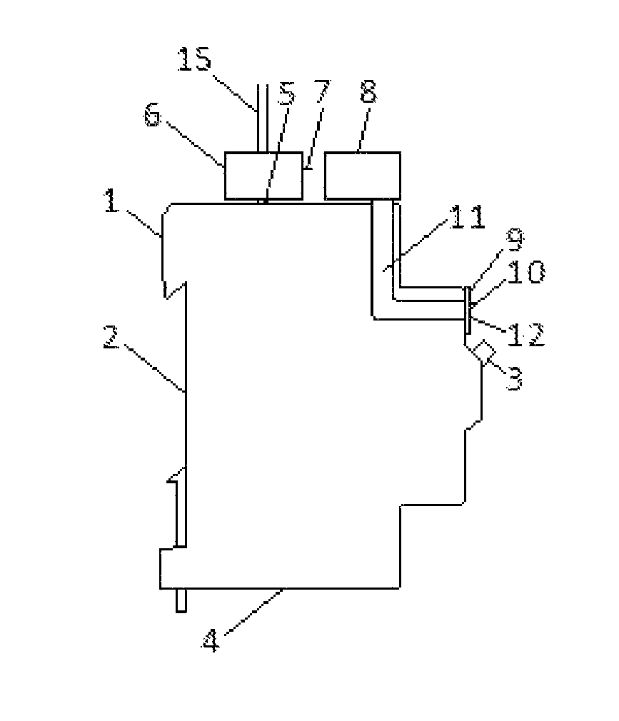
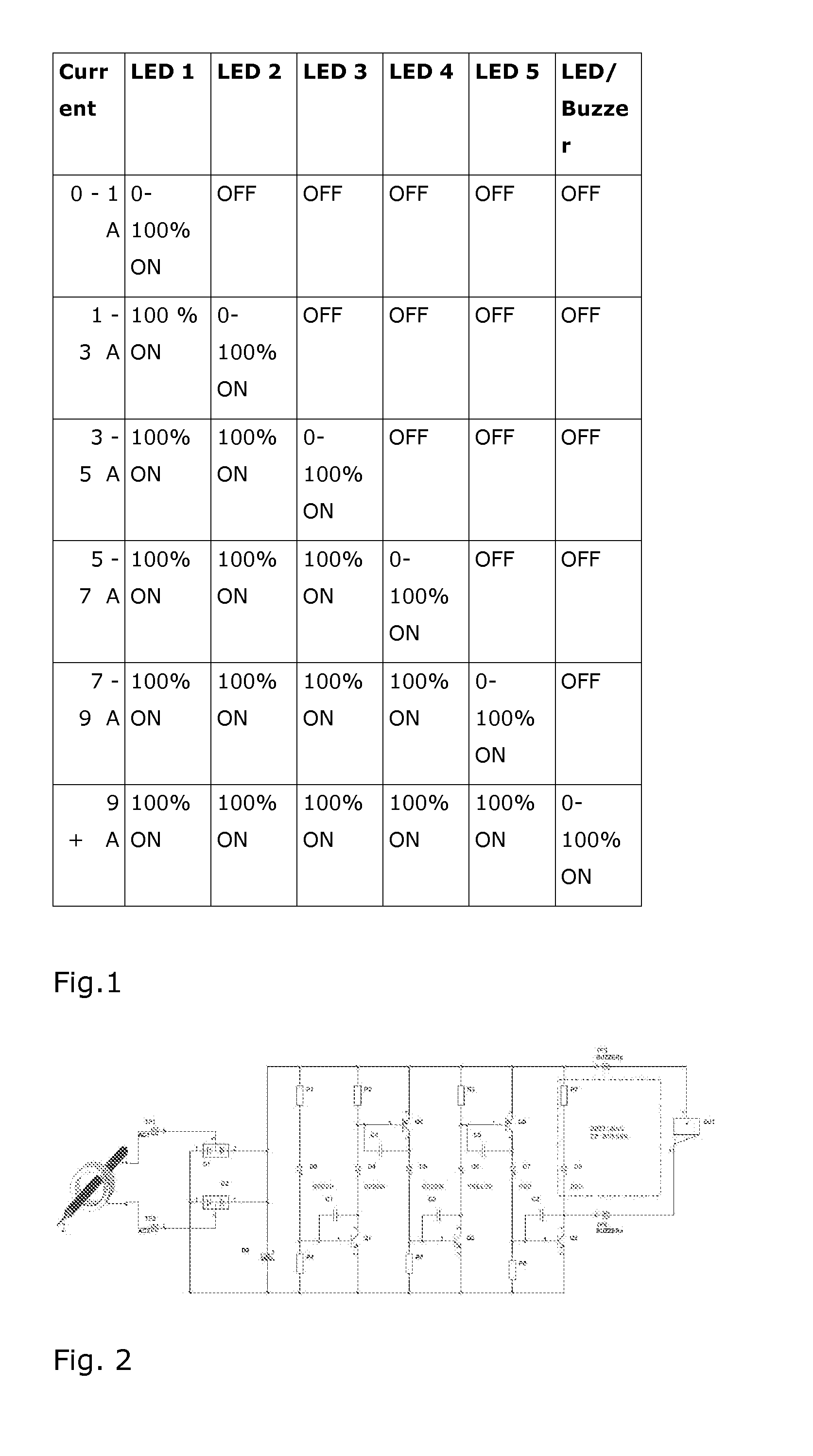
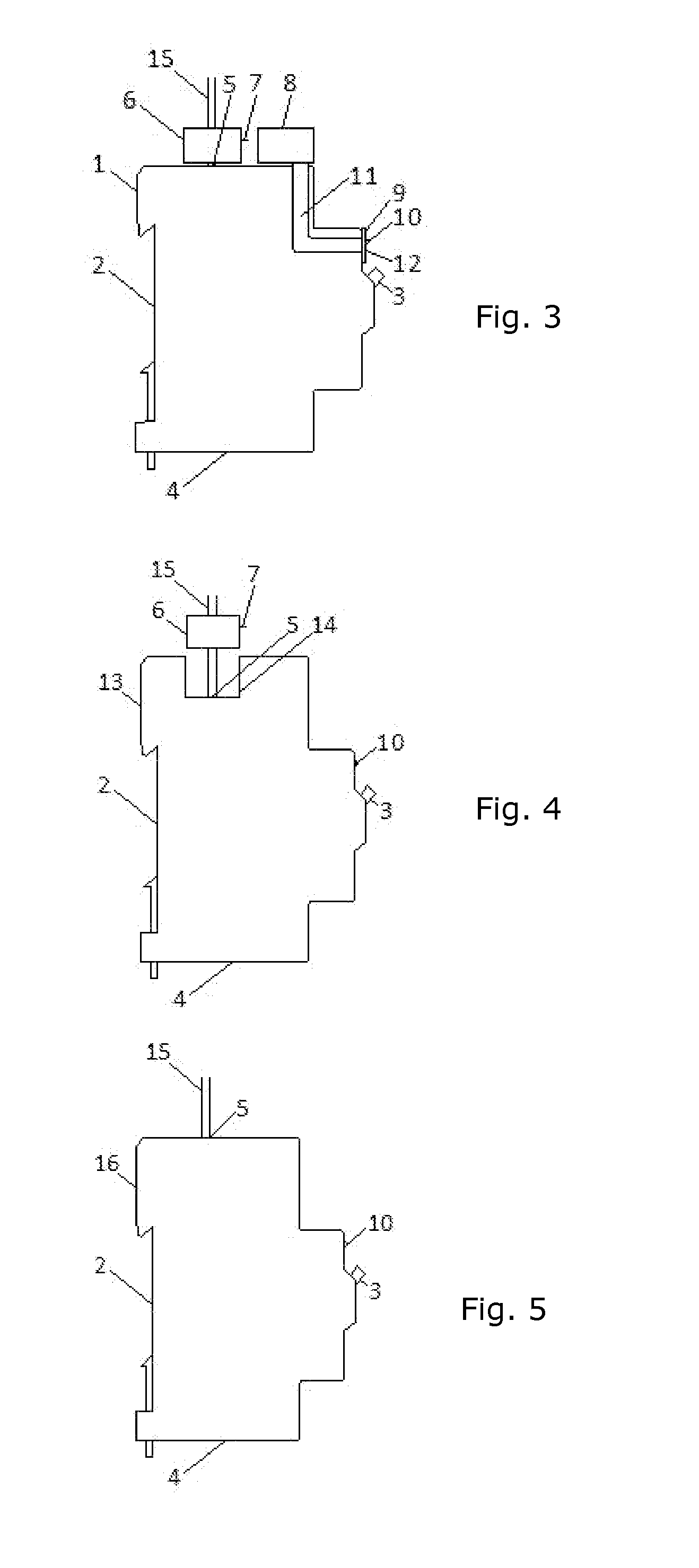
The present invention is a current metering device that can be added to a traditional circuit breaker to monitor the electrical load. The device uses LEDs to display the actual load in the circuit. The LEDs are arranged in a series, so the brighter they are, the higher the current. The device can also include a buzzer to alert to overload conditions. Overall, the device provides a convenient and effective way to monitor electrical usage and prevent equipment damage due to overuse or malfunctions.

Problems solved by technology

Furthermore, there also remains a need for providing an undemanding metering accessory to conventional circuit breakers in which can also transmit measurements to central processing units or computers.

Method used


Image

  • Circuit board meter for circuit breakers
  • Circuit board meter for circuit breakers
  • Circuit board meter for circuit breakers

Examples


Embodiment Construction

[0013]The advantage of the current metering device of the present invention is that a) a traditional (magnetic coil) current transformer is used to detect the current, which allows the metering device to detect the load and by producing reduced current accurately proportional to the current flowing through the circuit breaker, b) the CT is connected to an analogue circuit with one or more LEDs. The combination of a CT and the analogue circuit provides a measuring device for circuit breakers, which can handle a much greater load than current metering devices by resistor sensing effects such as meter shunts and Hall effects. A further advantage is that it can display gradual increase in load through intensity of illumination by the one or more LEDs or by turning on additional LEDs as the load increases. In addition to these advantages the electronic measuring circuit device of the present invention also has output means by “connection terminal” for conveying the current in the circuit...


PUM


Abstract

A current measuring device for circuit breakers with an improved electronic circuit arrangement by way of arrangement and method for displaying electrical line current by a circuit breaker wherein measurements are made by at least one current transformer. Indications of the magnitude of electrical current are displayed by at least one LED and by the intensity of illumination by each LED. The current measuring device is placed onto a circuit breaker wherein at least one LED of the improved circuit is made accessible by sight at the front face of the current measuring device attached to the circuit breaker. A current transformer is located inside the current measuring device attached to the circuit breaker for measuring the current flowing through the conductor applied to the circuit breaker. The current transformer supplies the improved electronic circuit with a reduced electrical current in proportion to the electrical current flowing through the conductor displaying the magnitude of the current by strength of illumination by at least one LED.

Description

FIELD OF THE INVENTION[0001]The present invention relates generally to electrical current level indication in conjunction with circuit breakers. More particularly but not exclusively, it relates to an electronic metering circuit accessory for indicating electrical current level in conjunction with circuit breakers.BACKGROUND OF THE INVENTION[0002]Circuit breakers are known in the art to be used to hold electrical line current and trip the current by overload or short circuit incidents. Circuit breakers generally have a switch to activate and / or deactivate electrical current connection through the circuit breakers, wherein the switch furthermore indicates an ON or OFF state of the circuit breaker to identify if electrical current is active or not. Because of these limited information means by circuit breakers integration of electrical measurements and indications have been provided by circuit breakers to provide information regarding electrical parameters by circuit breakers.[0003]Ci...

Claims


Application Information

Patent Timeline
IPC IPC(8): G01R19/15
CPCG01R19/0092G01R19/15H01H2071/042
Inventor JONSSON, HILMIR INGIOLAFSSON, JON THORHREGGVIDSSON, SNORRI
Owner REMAKE ELECTRIC EHF
Learn More