Repeater device

a repeater and radio channel technology, applied in multiplex communication, multiplex communication, frequency-division multiplex, etc., can solve the problems of amplitude and phase difference between the two links, severe affecting performance, and the assumption that the radio channel is reciprocal is not always true, so as to avoid the use of switches and timing units

Active Publication Date: 2013-08-29
TELEFON AB LM ERICSSON (PUBL)
View PDF4 Cites 12 Cited by
  • Summary
  • Abstract
  • Description
  • Claims
  • Application Information

AI Technical Summary

Benefits of technology

[0013]In another variation of the invention, the repeater arrangement comprises an amplifying device that comprises: a first circulator having a first port for connection to the first antenna; a second circulator having a first port for connection to the second antenna; a first amplifier connected at its input to a second port of the first circulator and at its output to a third port of the second circulator; a second amplifier connected at its output to a third port of the first circulator and at its input to a second port of the second circulator. In this embodiment, an alternative solution is provided for obtaining a reciprocal repeater, wherein the use of switches and timing unit is avoided.
[0014]In another variation of the above embodiment, a first filter device is included, connected at one end to the first port of the first circulator and at another end to the first antenna; and a second filter device connected at one end to the first port of the second circulator and at another end to the second antenna. By means of such filters, amplifier saturation outside antenna matched frequency band can be avoided.
[0015]In another variation of the above embodiment, a first attenuator is provided connected at one end to the first filter device and at one end to the first antenna, and a second attenuator connected at one end to the second filter device and at one end to the second antenna. The gain may thereby be adjusted when reflections are significant.

Problems solved by technology

However, the assumption that the radio channel is reciprocal is not always true.
However, due to non-coherent radio paths, used for DL and UL, respectively, there might be both amplitude and phase differences between the two links, introduced by the repeater.
The differences can severely affect performance.
For example, in a system in which channel weights in DL, based on UL signals, are designed for constructively adding signal components from different signal paths at the receiving end, the introduction of a repeater may destroy the reciprocity.
Amplitude and phase errors result from the false assumption that the channel is reciprocal and that the same channel state information can be used in uplink and downlink.
Due to these amplitude and phase errors, the signal components of the different paths may add up less efficiently or even destructively.
In short, the repeater introduces phase differences as well as amplitude differences, which is highly detrimental for the system performance.

Method used


Image

  • Repeater device
  • Repeater device

Examples


second embodiment

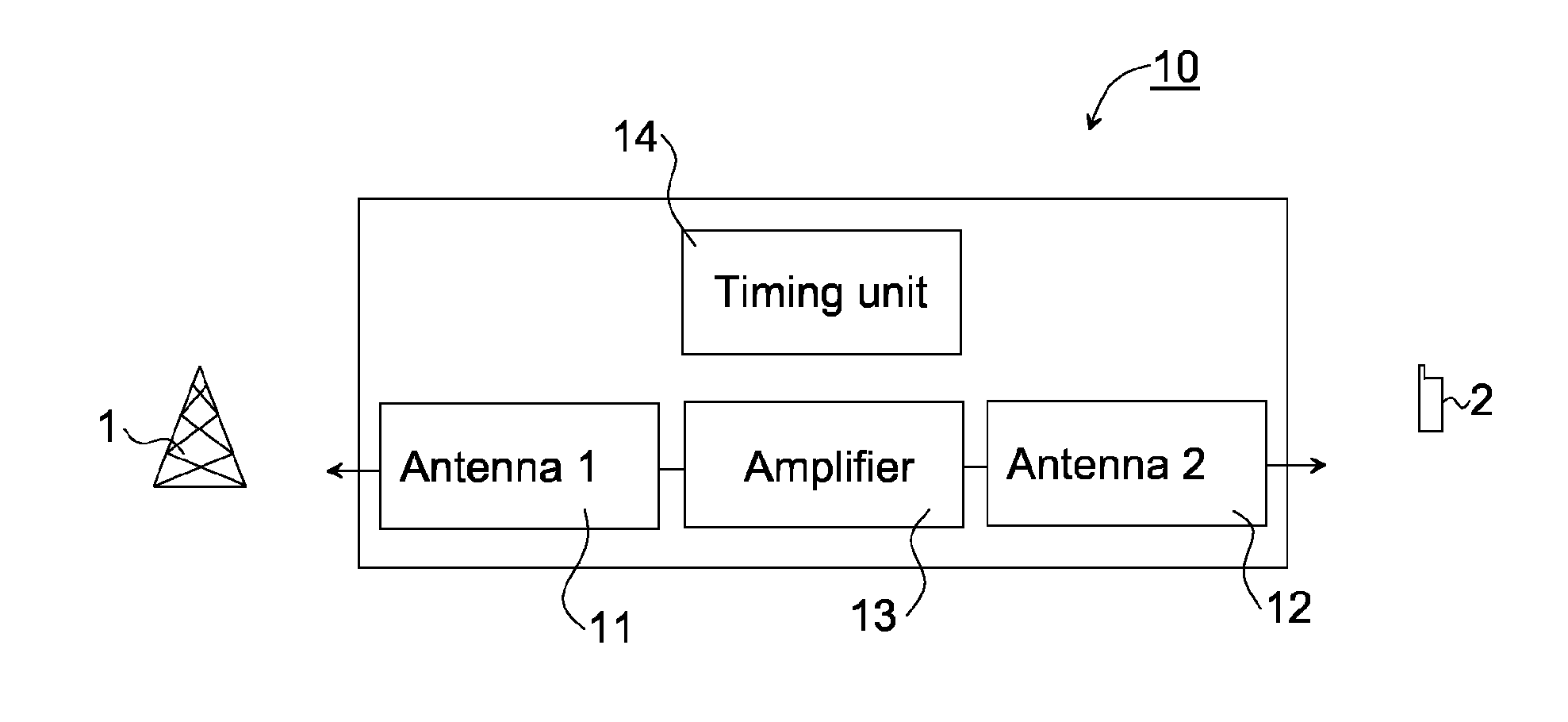
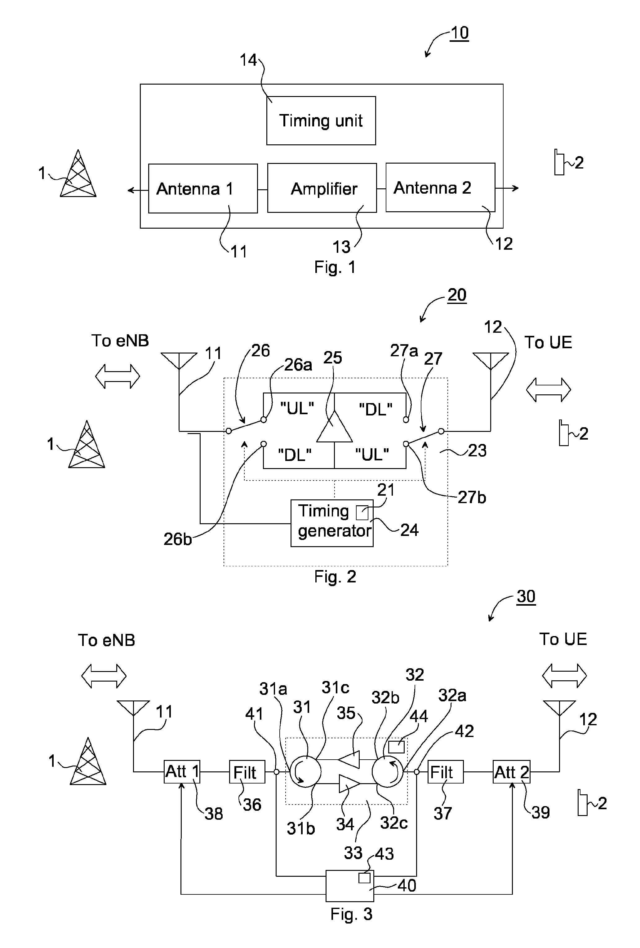
[0034]FIG. 2 illustrates the present invention. The repeater arrangement 20 comprises the first antenna 11 and the second antenna 12 as above. In this embodiment, an amplifying device 23 comprises switches 26, 27 that are selectively switchable for electrically connecting the first and second antennas 11, 12 to the first signal path and the second signal path, respectively.

[0035]In particular, the amplifying device 23 comprises a first switch 26 having a first position 26a and a second position 26b, and further a second switch 27 having a first position 27a and a second position 27b. When the first switch 26 is switched in its first position 26a and the second switch 27 is switched in its second position 27b, a signal path through the amplifying device 23 is provided for the UL. In particular, the communication signal received at the second antenna 12 is, with the switches in these positions, led through an amplifier 25 to the first antenna 11, the communication signal being amplifi...

third embodiment

[0043]FIG. 3 illustrates the present invention. In this embodiment, the use of a timing unit is avoided, as is the use of switches.

[0044]The repeater arrangement 30 comprises the first antenna 11 and the second antenna 12 as above. An amplifying device 32 of this embodiment comprises a first circulator 31 and a second circulator 32, both circulators being three-port devices, each having a first, a second and a third port, 31a, 31b, 31c and 32a, 32b, 32c, respectively. The first circulator 31 has a first port 31a for connection to the first antenna 11, and a second circulator 32 has a first port 32a for connection to the second antenna 12.

[0045]The repeater arrangement 30 comprises a first amplifier 34 and a second amplifier 35, both operatively connected between the first and the second circulators 31, 32. In particular, the first amplifier 34 is connected at its input to the second port 31b of the first circulator 31 and at its output to the third port 32c of the second circulator ...


PUM


Abstract

The invention relates to a repeater arrangement for amplifying a communication link between a base station and user equipment, wherein the communication link comprises an uplink and a downlink utilizing frequencies within a coherence bandwidth. The repeater arrangement comprises: a first antenna for communication with the base station; a second antenna for communication with the user equipment; an amplifying device operatively connected to the first antenna and to the second antenna for conveying and amplifying communication signals between the first antenna and the second antenna, the amplifying device comprising a first signal path for the uplink and a second signal path for the downlink, the first and second signal paths having equal electrical length, in order to affect said communication signal identically in both uplink and downlink, providing same phase and amplitude characteristics to said communication signal.

Description

FIELD OF THE INVENTION[0001]The present invention relates generally to the field of wireless communication, and in particular to arrangements for amplifying signaling between wireless communicating parties.BACKGROUND OF THE INVENTION[0002]In any wireless communication system, a signal transmitted from one signaling part to another is distorted due to dynamic properties of a radio channel through which it is transmitted. The radio channel between a transmitter and a receiver can be characterized by channel state information describing how the signal propagates from the transmitter to the receiver. The channel state information is estimated at the receiver and conveyed to the transmitter, and used for compensating e.g. for scattering, fading and power level reduction related to distance between the transmitter and receiver.[0003]In a time division duplex (TDD) based communication system, reciprocity between downlink (DL, signaling from base station to user equipment) and uplink (UL, s...

Claims


Application Information

Patent Timeline
Patent Type & Authority Applications(United States)
IPC IPC(8): H04W16/26
CPCH04W16/26H04B7/155
Inventor MEDBO, JONASPETERSSON, SVENZANGI, KAMBIZ
Owner TELEFON AB LM ERICSSON (PUBL)
Why Eureka
Try Eureka