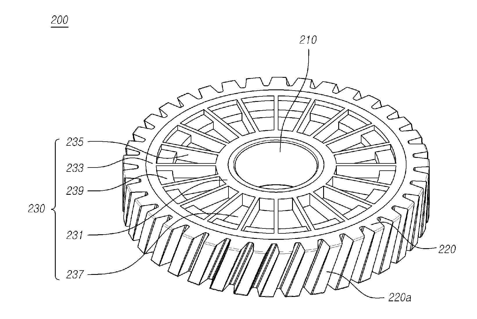
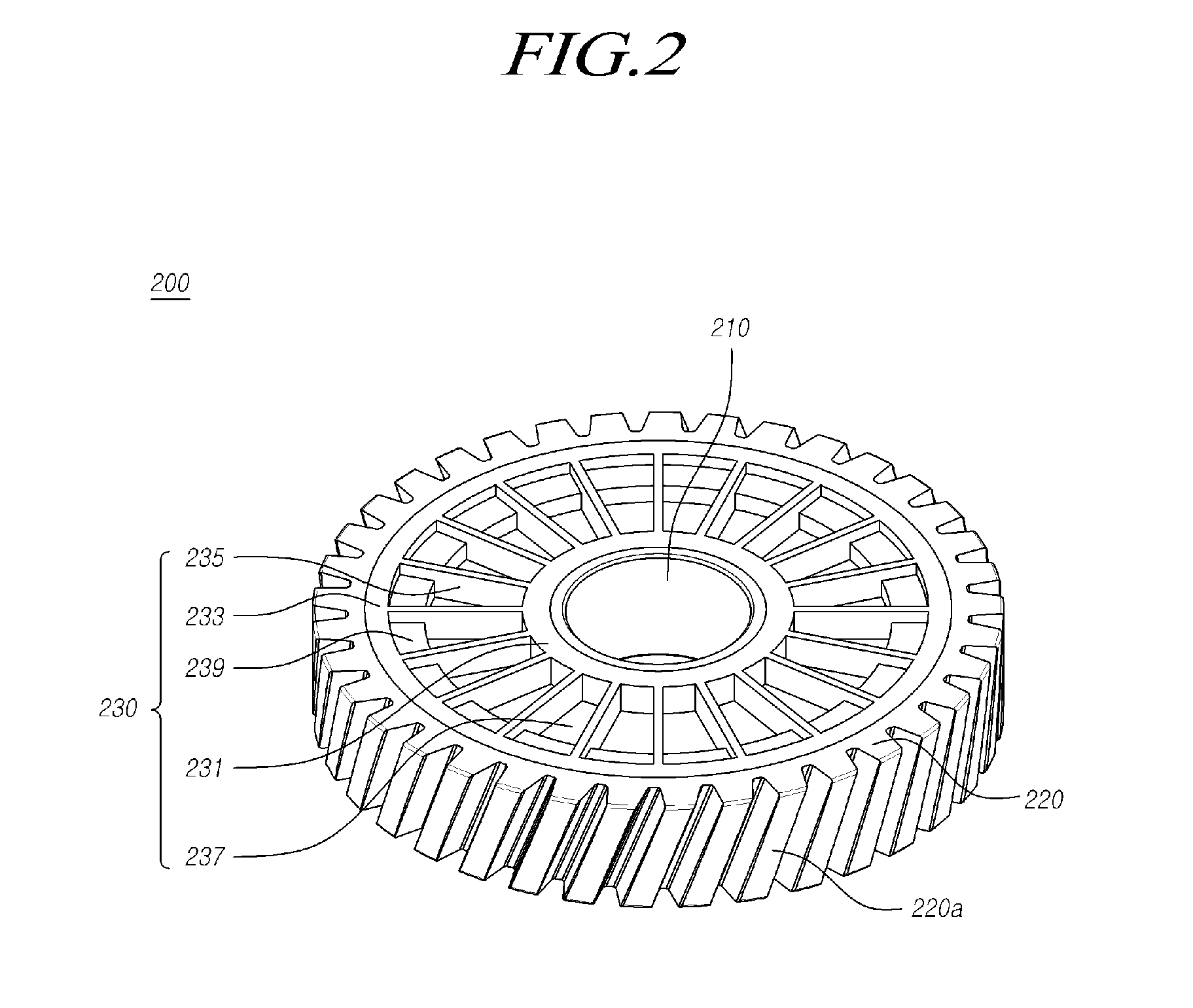
Worm wheel for electric power steering apparatus and method for manufacturing the same

a technology of electric power steering and worm wheel, which is applied in the direction of hoisting equipment, transportation and packaging, and other domestic objects, can solve the problems of deteriorating forming performance, material cost increase, and damage to parts, so as to increase the mechanical durability and frictional characteristics increase the forming performance of the worm wheel, and reduce the amount of material

Inactive Publication Date: 2013-09-05
HL MANDO CORP
View PDF8 Cites 42 Cited by
  • Summary
  • Abstract
  • Description
  • Claims
  • Application Information

AI Technical Summary

Benefits of technology

[0015]Accordingly, the present invention has been made to solve the above-mentioned problems occurring in the prior art, and an object of the present invention is to provide a worm wheel of a reducer of an electric power steering apparatus which is manufactured by integrally injection-molding a hub, a boss, and a gear forming part, thereby making it possible to increase a forming performance of the worm wheel and reduce an amount of material, and increasing a mechanical durability and frictional characteristics of the worm wheel to allow the reducer to to be stably used for a long time, and a method for manufacturing the same.
[0024]As described above, according to the present invention, a worm wheel of a reducer of an electric power steering apparatus can be manufactured by integrally injection-molding a hub, a boss, and a gear forming part, thereby making it possible to increase a forming performance of the worm wheel and reduce an amount of material, and increasing a mechanical durability and frictional characteristics of the worm wheel to allow the reducer to be stably used for a long time.

Problems solved by technology

However, when the worm wheel of the reducer is formed of a resin composition, forming performance deteriorates and material costs increase.
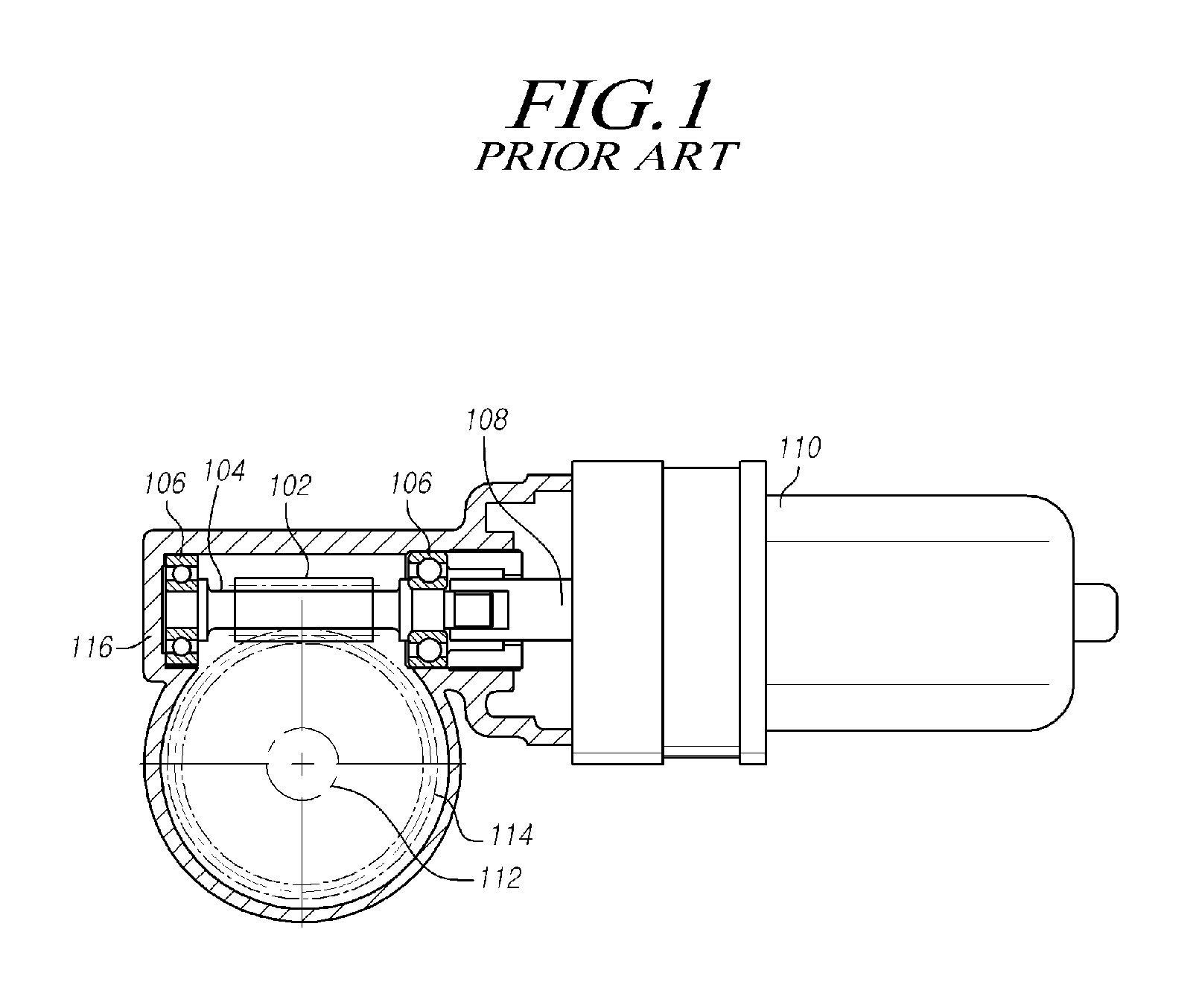
Further, since the worm shaft, the worm wheel, and the steering shaft rotated together are engaged with each other, a torsion load and vibrations generated by the rotations may be severely transmitted, deteriorating durability of parts or damaging parts in violent cases.
In particular, when the vehicle travels on an uneven road, a load transmitted from a wheel via a rack bar and a steering shaft may increase instantaneously, deforming or damaging their shapes, which may cause a safety accident to the driver.

Method used


Image

  • Worm wheel for electric power steering apparatus and method for manufacturing the same
  • Worm wheel for electric power steering apparatus and method for manufacturing the same
  • Worm wheel for electric power steering apparatus and method for manufacturing the same

Examples


Embodiment Construction

[0031]Hereinafter, exemplary embodiments of the present invention will be described with reference to the accompanying drawings. In the following description, the same elements will be designated by the same reference numerals although they are shown in different drawings. Further, in the following description of the present invention, a detailed description of known functions and configurations incorporated herein will be omitted when it may make the subject matter of the present invention rather unclear.

[0032]In addition, terms, such as first, second, A, B, (a), (b) or the like may be used herein when describing components of the present invention. Each of these terminologies is not used to define an essence, order or sequence of a corresponding component but used merely to distinguish the corresponding component from other component(s). It should be noted that if it is described in the specification that one component is “connected”, “coupled” or “joined” to another component, a ...


PUM

PropertyMeasurementUnit
diameteraaaaaaaaaa
distanceaaaaaaaaaa
mechanical durabilityaaaaaaaaaa

Abstract

Disclosed is a worm wheel of a reducer of an electric power steering apparatus which is manufactured by integrally injection-molding a hub, a boss, and a gear forming part, thereby making it possible to increase a forming performance of the worm wheel and reduce an amount of material, and increasing a mechanical durability and frictional characteristics of the worm wheel to allow the reducer to be stably used for a long time, and a method for manufacturing the same.

Description

CROSS-REFERENCE TO RELATED APPLICATION[0001]This application claims priority from and the benefit uncle-35 U.S.C. §119(a) of Korean Patent Application No. 10-2012-0021570, filed on Mar. 2, 2012, which is hereby incorporated by reference for all purposes as if fully set forth herein.BACKGROUND OF THE INVENTION[0002]1. Field of the Invention[0003]The present invention relates to a worm wheel for an electric power steering apparatus and a method for manufacturing the same, and more particularly to a worm wheel of a reducer of an electric power steering apparatus which is manufactured by integrally injection-molding a hub, a boss, and a gear forming part, thereby making it possible to increase a forming performance of the worm wheel and reduce an amount of material, and increasing a mechanical durability and frictional characteristics of the worm wheel to allow the reducer to to be stably used for a long time, and a method for manufacturing the same.[0004]2. Description of the Prior Art...

Claims


Application Information

Patent Timeline
Patent Type & Authority Applications(United States)
IPC IPC(8): F16H55/17
CPCB62D5/0409F16H55/06Y10T74/1987F16H2055/065F16H55/17F16H55/22B29C45/1459B29C45/1671B29C45/2708B29L2015/003B62D3/04B62D5/24
Inventor KIM, SEONG SOOAHN, HEE CHUL
Owner HL MANDO CORP
Why Eureka
Try Eureka