Substrate support with ceramic insulation

a technology of ceramic insulation and substrate, applied in the direction of coatings, chemical vapor deposition coatings, electric discharge tubes, etc., can solve the problems of arcing, difficulty in fabricating the various chamber components out difficulty in forming the various chamber components of a unitary piece, so as to reduce the arcing

Active Publication Date: 2013-09-05
APPLIED MATERIALS INC
View PDF11 Cites 19 Cited by
  • Summary
  • Abstract
  • Description
  • Claims
  • Application Information

AI Technical Summary

Benefits of technology

[0008]Embodiments of the present invention generally relates to substrate supports for use in a plasma processing chamber. The substrate supports, which are metallic, have ceramic inserts to prevent arcing between the substrate support and the shadow frame used to protect the edges of the substrate support during processing. In large area substrate processing chambers, the shadow frame may comprise multiple pieces. The individual pieces may be coupled together, but spaced slightly apart by a gap to permit thermal expansion. Ceramic inserts are positioned on the substrate support so that when a shadow frame is positioned adjacent thereto, the ceramic inserts are located adjacent the gaps in the shadow frame. The ceramic inserts adjacent the gap prevent and / or reduce the arcing because the gaps are located over electrically insulating material rather than electrically conductive material.

Problems solved by technology

As most FPDs are rectangular in shape, a processing chamber designed to process circular shaped substrates, such as semiconductor wafers, may not be desirable due to the amount of wasted substrate that would need to be removed to form the final shape of the rectangular FPD.
As the large area processing chambers continue to increase in size, fabricating the various chamber components out of a unitary piece become difficult.
Each piece may expand and contract due to thermal expansion issues.
If the pieces are biased, arcing can easily occur within the chamber.

Method used


Image

  • Substrate support with ceramic insulation
  • Substrate support with ceramic insulation
  • Substrate support with ceramic insulation

Examples


Embodiment Construction

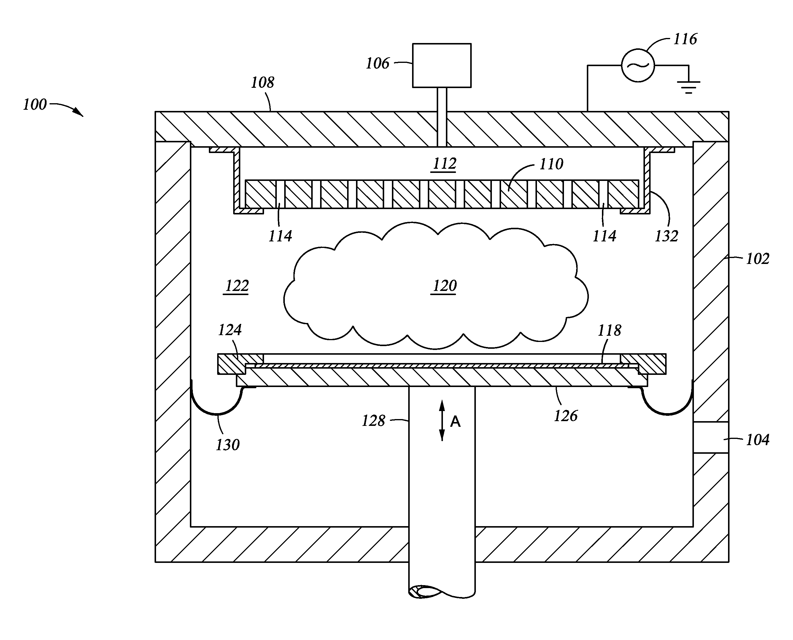
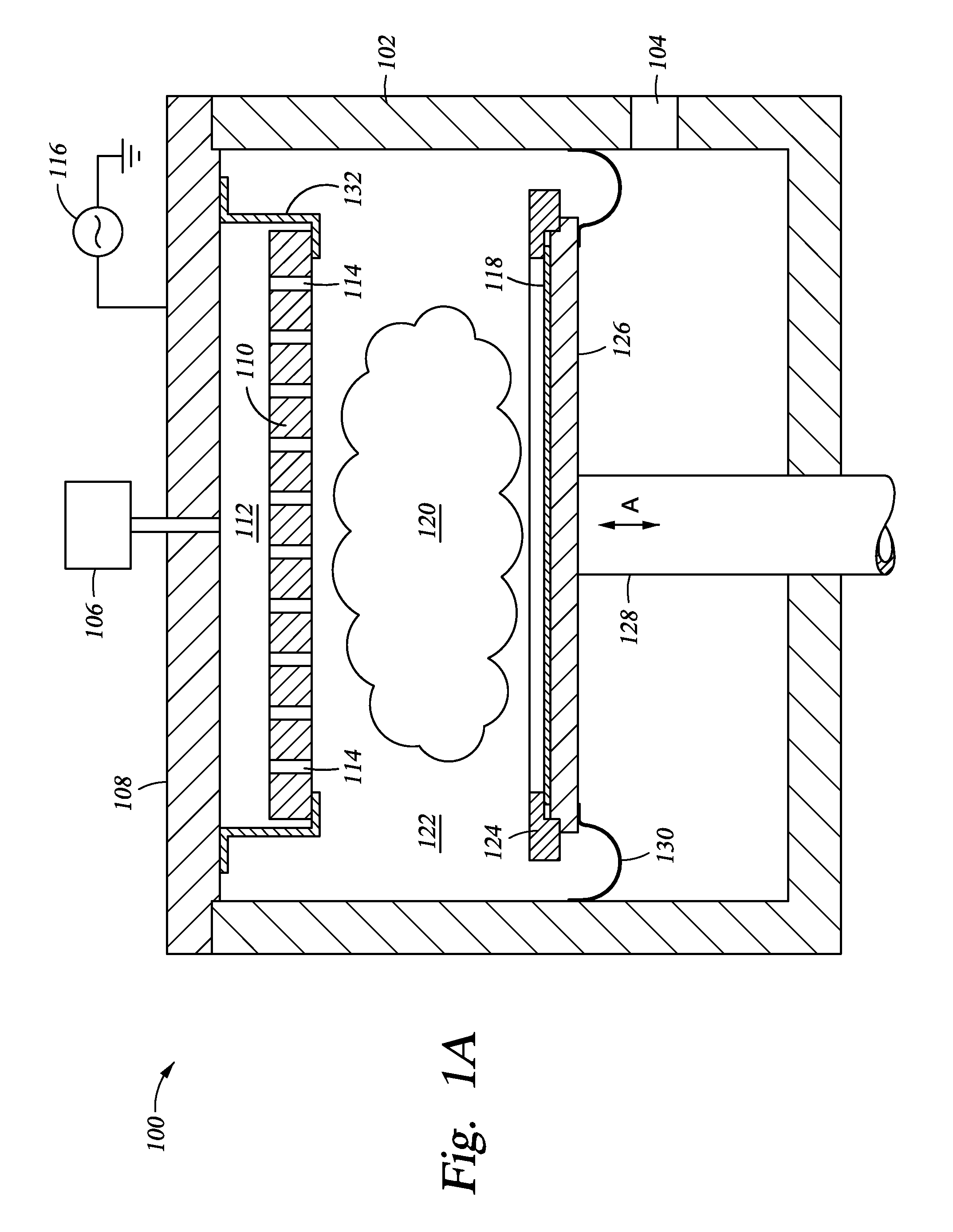
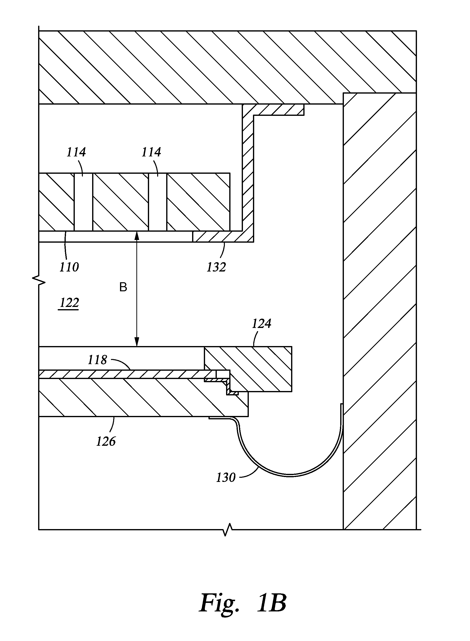
[0019]Embodiments of the present invention generally relates to substrate supports for use in a plasma processing chamber. The substrate supports, which are metallic, have ceramic inserts to prevent arcing between the substrate support and the shadow frame used to protect the edges of the substrate support during processing. In large area substrate processing chambers, the shadow frame may comprise multiple pieces. The individual pieces may be coupled together, but spaced slightly apart by a gap to permit thermal expansion. Ceramic inserts are positioned on the substrate support so that when a shadow frame is positioned adjacent thereto, the ceramic inserts are located adjacent the gaps in the shadow frame. The ceramic inserts adjacent the gap prevent and / or reduce the arcing because the gaps are located over electrically insulating material rather than electrically conductive material.

[0020]Description below will be made with reference to a plasma enhanced chemical vapor deposition...


PUM

PropertyMeasurementUnit
metallicaaaaaaaaaa
thicknessaaaaaaaaaa
lengthaaaaaaaaaa

Abstract

Embodiments of the present invention generally relates to substrate supports for use in a plasma processing chamber. The substrate supports, which are metallic, have ceramic inserts to prevent arcing between the substrate support and the shadow frame used to protect the edges of the substrate support during processing. In large area substrate processing chambers, the shadow frame may comprise multiple pieces. The individual pieces may be coupled together, but spaced slightly apart by a gap to permit thermal expansion. Ceramic inserts are positioned on the substrate support so that when a shadow frame is positioned adjacent thereto, the ceramic inserts are located adjacent the gaps in the shadow frame. The ceramic inserts adjacent the gap prevent and / or reduce the arcing because the gaps are located over electrically insulating material rather than electrically conductive material.

Description

CROSS-REFERENCE TO RELATED APPLICATIONS[0001]This application claims benefit of U.S. Provisional Patent Application Ser. No. 61 / 606,729 (APPM / 16808L), filed Mar. 5, 2012, which is herein incorporated by reference.BACKGROUND OF THE INVENTION[0002]1. Field of the Invention[0003]Embodiments of the present invention generally relate to substrate supports for use in a plasma processing chamber.[0004]2. Description of the Related Art[0005]Televisions, computer monitors and other flat panel displays (FPDs) are typically fabricated in large area substrate processing chambers. These large area processing chambers are designed to process rectangular shaped substrates in order to maximize the effective use of the substrate. As most FPDs are rectangular in shape, a processing chamber designed to process circular shaped substrates, such as semiconductor wafers, may not be desirable due to the amount of wasted substrate that would need to be removed to form the final shape of the rectangular FPD....

Claims


Application Information

Patent Timeline
Patent Type & Authority Applications(United States)
IPC IPC(8): C23C16/458
CPCH01J37/32559H01J37/32577C23C16/458C23C16/4585H01J37/32715
Inventor FURUTA, GAKUWHITE, JOHN M.KURITA, SHINICHICHOI, SOO YOUNGANWAR, SUHAILTINER, ROBIN L.
Owner APPLIED MATERIALS INC
Why Eureka
Try Eureka