
Dual pressure sensor continuous positive airway pressure (CPAP) therapy

a positive airway pressure and dual pressure sensor technology, applied in the direction of valves, mechanical equipment, operating means/releasing devices, etc., can solve the problems of reduced blood oxygen saturation, additional discomfort, and patient discomfort, and achieve the effect of reducing mask pressure and reducing the amount of therapeutic airflow

Active Publication Date: 2013-09-05
BREATHE TECHNOLOGIES INC
View PDF15 Cites 35 Cited by
  • Summary
  • Abstract
  • Description
  • Claims
  • Application Information

AI Technical Summary

Benefits of technology

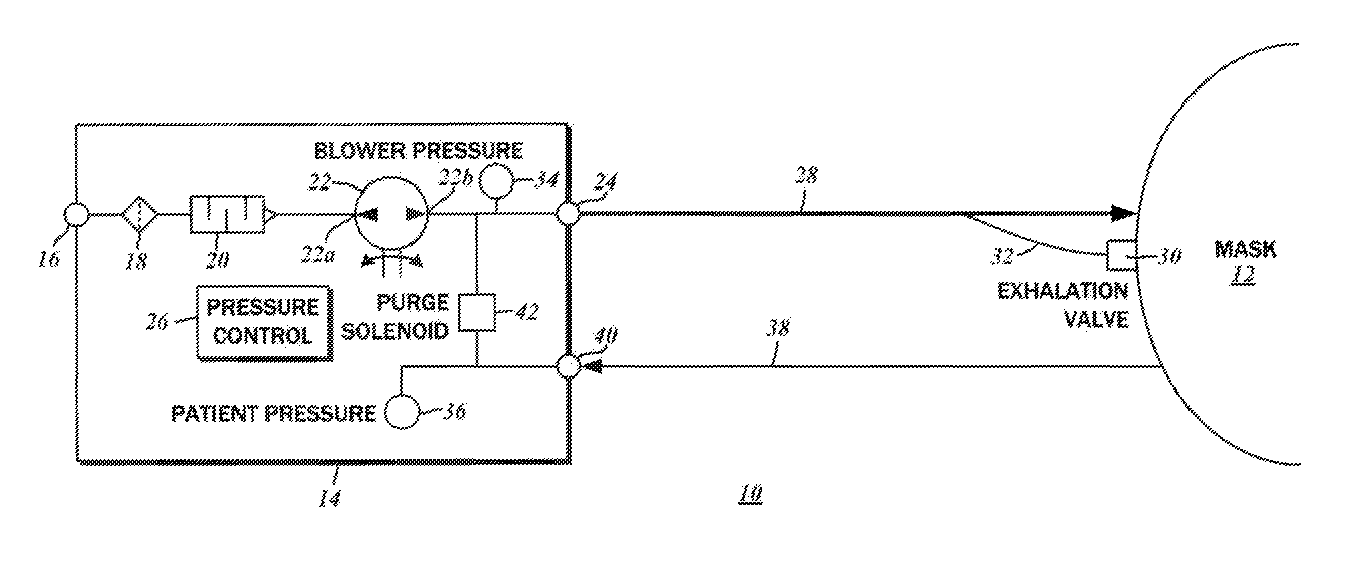
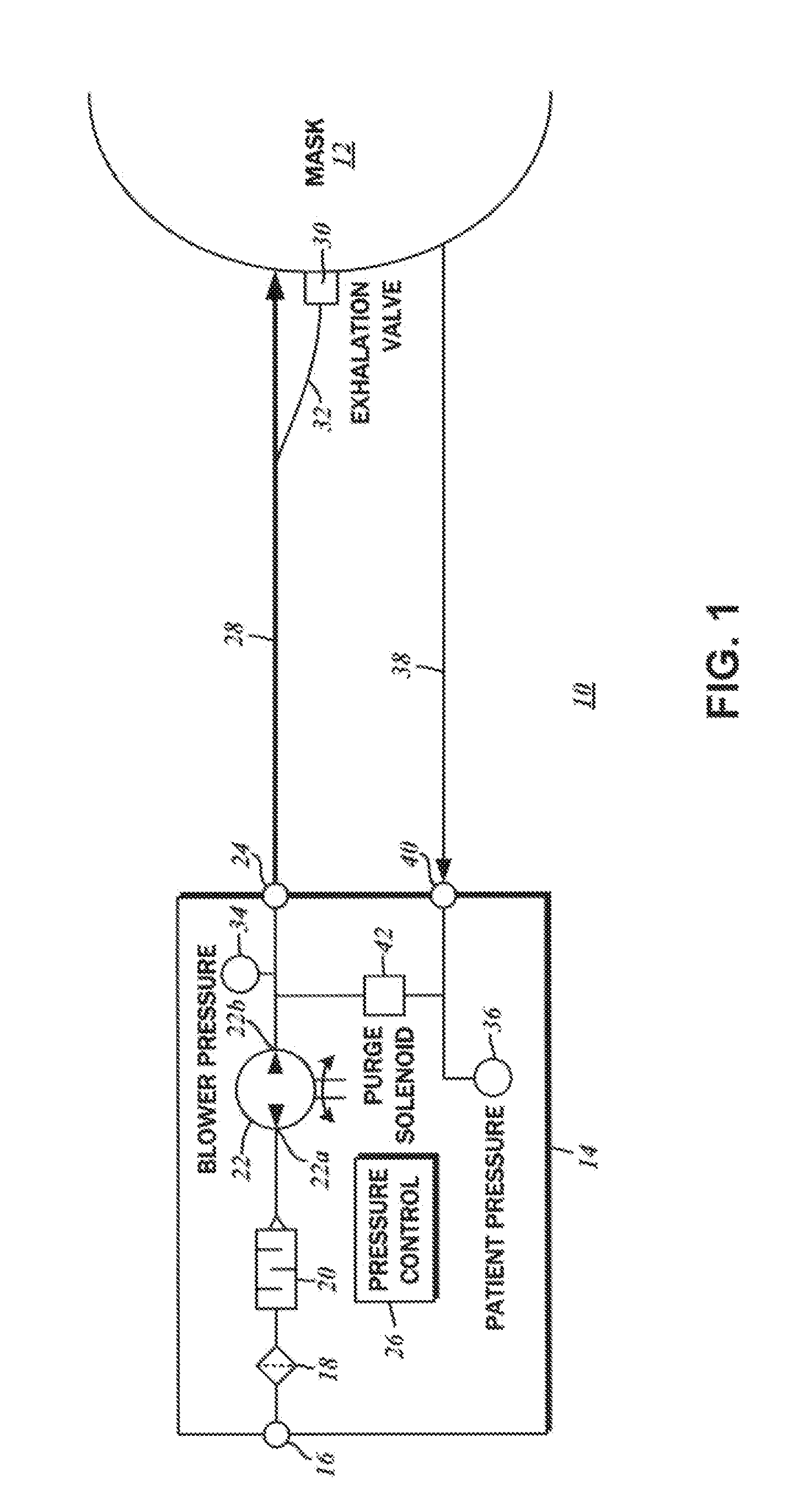
This patent is about a respiratory assistance device that includes a blower and a patient ventilation interface with a pilot-operated exhalation valve. The device has two pressure sensors that measure the pressure in the mask and the blower, and a pressure controller that regulates the therapeutic airflow delivered to the patient based on these pressure differences. The device can also relieve mask pressure by reducing the therapeutic airflow delivered to the patient. The technical effect of this device is to improve respiratory therapy by providing precise control of airflow to patients in need.

Problems solved by technology

However, the vast majority of contemporary ventilators instead use positive pressure to deliver gas to the patient's lungs via a patient circuit between the ventilator and the patient.
Although some degree of apnea is considered normal, in more severe cases, daytime sleepiness and fatigue may result as a consequence of reduced blood oxygen saturation, as well as constant interruptions to sleep cycles.
However, supplying positive pressure flow into the patient during the expiratory phase generates resistance to the patient's breathing efforts, causing discomfort.
Furthermore, toward the end of the patient's expiratory phase, flow and pressure in the airway is naturally minimal, such that positive pressure can cause additional discomfort.
Although the method disclosed by Estes, et al. allows the delivered therapeutic pressure to the patient to be tuned to a greater degree, the patient nevertheless experiences discomfort.
However, due to the wind-up and wind-down times associated with starting and stopping an electrical motor, patient comfort is not optimized due to the existence of residual pressure.

Method used


Image

  • Dual pressure sensor continuous positive airway pressure (CPAP) therapy
  • Dual pressure sensor continuous positive airway pressure (CPAP) therapy
  • Dual pressure sensor continuous positive airway pressure (CPAP) therapy

Examples


Embodiment Construction

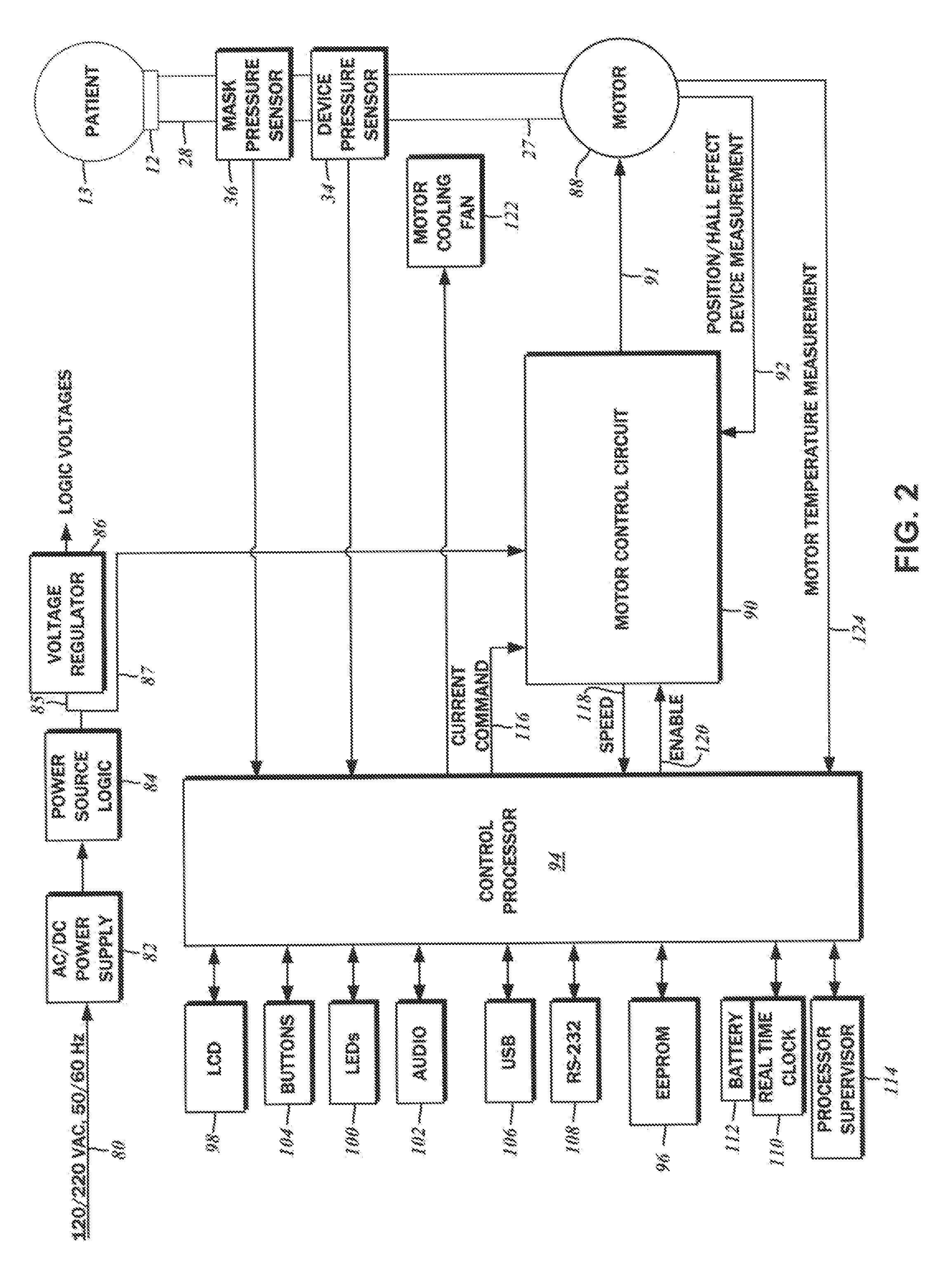
[0028]The detailed description set forth below in connection with the appended drawings is intended as a description of the several presently contemplated embodiments of a system for continuous positive airway pressure (CPAP) therapy. The system delivers breathing gas to a patient for the treatment of obstructive sleep apnea (OSA) and other cardio-pulmonary conditions, and implements various methods for the selective pressure augmentation and relief throughout the breathing cycle. This description is not intended to represent the only form in which the disclosed invention may be developed or utilized. The description sets forth the functions and features in connection with the illustrated embodiments. It is to be understood, however, that the same or equivalent functions may be accomplished by different embodiments that are also intended to be encompassed within the scope of the present disclosure. It is further understood that the use of relational terms such as first and second an...


PUM


Abstract

A continuous positive airway pressure (CPAP) apparatus for respiratory assistance of a pattern is disclosed. There is a blower having an output connectible to a ventilation mask wearable by the patient. A first pressure sensor measures blower pressure at the output of the blower, and a second pressure sensor that is connectible to the ventilation mask measures mask pressure therein. A pressure controller is connected to the first pressure sensor and the second pressure sensor, and a patient inspiratory phase and a patient expiratory phase is be detectable by the pressure controller to regulate therapeutic pressure at the patient mask, based upon pressure differentials between the mask pressure and the blower pressure.

Description

CROSS-REFERENCE TO RELATED APPLICATIONS[0001]Not ApplicableSTATEMENT RE: FEDERALLY SPONSORED RESEARCH / DEVELOPMENT[0002]Not ApplicableBACKGROUND OF THE INVENTION[0003]1. Field of the Invention[0004]The present disclosure relates generally to the treatment of respiratory and cardiovascular conditions, and more particularly, to methods and systems for continuous positive airway pressure (CPAP) therapy selectively providing a pressurized flow of breathable gas to a patient utilizing dual pressure sensors at a source and on a ventilation mask.[0005]2. Description of the Related Art[0006]Mechanical ventilators comprise medical devices that either perform or supplement breathing for patients. Early ventilators, such as the “iron lung,” created negative pressure around the patient's chest to cause a flow of ambient air through the patient's nose and / or mouth into the lungs. However, the vast majority of contemporary ventilators instead use positive pressure to deliver gas to the patient's l...

Claims


Application Information

Patent Timeline
Patent Type & Authority Applications(United States)
IPC IPC(8): A61M16/06A61M16/20
CPCA61M16/20A61M16/00A61M2016/0021A61M2016/0027A61M2205/18A61M16/107A61M2205/3365A61M2205/3368A61M2205/42A61M2205/502A61M16/0069A61M2205/3355A61M16/0051A61M16/201A61M16/026A61M16/022A61M16/024A61M16/021
Inventor AHMAD, SAMIR S.BALAO WELZIEN, LEONARDO ALBERTOBRAMBILLA, ENRICO
Owner BREATHE TECHNOLOGIES INC
Learn More